OpenSource ROV
For a summary of the most recent changes in the designs previously posted please look at this page: ROV Project Updates.
This project was originally inspired by a conversation I had with some scientists at Industrial Research limited (one of New Zealand’s Government Scientific Institutes). They were developing a wave energy device and were partly funded by the Marine Energy Deployment Fund that EECA was running. I was EECA’s Renewable Energy engineer at the time. The conversations ran something like this “….. it costs us $50000 just to get a diver into the water each time we want to look at it …..” and then went on to ask for more money. Sure they would have been exaggerating a little bit but even so, this got me to thinking that there was an opportunity for a cheap ROV that could be chucked over the side of a small runabout and allow the owner of a marine energy device, marine farm, or sub-sea system to quickly and cheaply do their check and then decide whether they need to get divers out. So the idea started there and that made me aware of the various ROV projects out there, the OpenROV project among them.
My Partner was keen that we purchase an OpenROV - which we did. Almost a year later having battled to find batteries that suit it (Not Available in New Zealand), leaks even under 200mm of water, unreliable communication with the OpenROV and having to buy a powerful laptop just to handle the video feed, it is still not running. In my view there are a lot of fundimental design flaws in the OpenROV device. With my frustration with the OpenROV I decided to continue with my original plan to design and build my own ROV that would hopefully be more robust, and reliable than the OpenROV as well as more accessable through the use of equipment that is more easily available worldwide. About the only idea that may be carried over from the OpenROV project is the thruster arrangement, but even they may get ditched in favour of modified submersible bilge pumps or the motors being sealed in oil filled capsules.
That’s the history about why this project has arisen.
The information described below is the summary of the work to date and will change as development continues. Each subsystem is described in as much detail as I can in the hope of making it easy to understand and for others to pick up and run with it.
Control System
The control system is intended to be very simple to ensure that it is easy to modify, affordable, reliable, and robust. For this reason I have adopted a system with two arduinos communicating to eachother over a 100m length of CAT5 cable using serial commands. The information being exchanged between the two arduinos is just data to control the lights and camera and to convey the positions of the joysticks on the handset controller (Playstation2 Controller) to the motors onboard. Voltage of the batteries within the ROV will be returned to the controlling Arduino for display. At this stage a depth sensor has not been included but there is spare capacity on the ROV Arduino to connect in extra sensors such as this. Below is the description of the circuits and Arduino sketches to get the topside station successfully controlling the ROV systems via communication through the 100m tether.
and the Calibration Sketch which is required to set up the Electronic Speed Controllers.
Also this useful circuit to keep an eye on your topside battery so it does not go flat on you.
Superceded Editions
- ROV Control Sketches and Circuits - Third Edition
- ROV Control Sketches and Circuits - Second Edition
- ROV Control Sketches and Circuits - First Edition
- ROV Electronics
The pages below are some of the development work to check that communications could be sent the 100m long CAT5 cable, look at using Playstation2 handsets to provide control to a device that accepts servo commands, and test out various sensors.
- Using PS2 Controllers for the User Interface
- Communication between Arduinos over a long cable
- Communication between Arduinos over a not particularly long cable using I2C
- Calibration of a Single HobbyKing® ™ 10A Brushless Car ESC
- Calibration of all ROV ESCs - Superceded
- Two Way Serial Communication
- PS2 Controllers Actuating servos and Switches
- HMC5883L Digital Compass on an Arduino
- ROV Thumb Twiddling Sketch
A number of Arduino Libraries are used in these developments. You can download these from the following webpage: A Collection of Arduino Libraries Used in This Project.
Video System
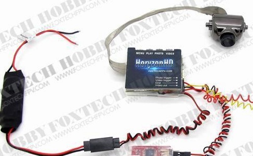
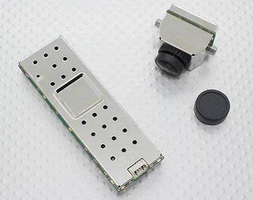
The video system is completely separate from the control system other than some controls to activate and deactivate recording and to take photos. This means that a simple system can be used and any video display device can be used at the users end and it is not impeded by processing time as it may be if passed through a computer. Initially a separate pilot camera and recordering camera were going to be used, but the FPV cameras are developing at a remarkable speed which has meant that some very sophisticated and yet cheap cameras are available that can do both jobs on the same unit. In particular the HoryzonHD Full HD 1080p FPV camera V3 sold by FoxtechFPV and the Boscam Cobra HD FPV camera with Integrated Video Recorder 1080P (Hobbyking stock this) are ideal. The design presented here makes use of the Horyzon camera but will accommodate the Boscam with a slight modification to the panels that support the digital video recorder module.
The HD Full HD 1080p FPV camera V3 - image from the FoxtechFPV website.
The Boscam Cobra HD FPV camera with Integrated Video Recorder 1080P - image from the Hobbyking website
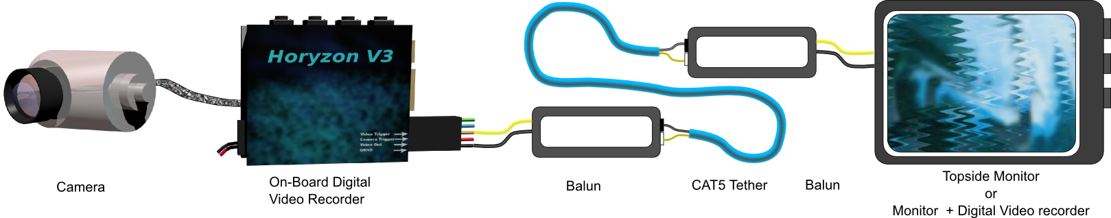
- Sending video over long cables using Passive Baluns
- Arduino Sketch to control the HoryzonHD V3 Camera
Thrusters
At this stage there are three ideas for thrusters under consideration. The simplest is the Outrunner Brushless DC motor arrangement used by the OpenROV, the second is a number of submersible bilge pumps, and the third is an Open Source Thruster design.
Shell and Structure
The shell is a 350mm length of 100mmNB uPVC PN15 pressure pipe. 4mm threaded rod running the length of the shell will be used to compress the end caps onto some O-rings. The depth limit for the shell is supposedly about 130m or so … if I have done my calculations correctly. This is in active development so check back from time to time if you are interested in this project. You can find the analysis of the ROV shell and end caps on the webpages below as well as the methods investigated to achieve a reliable seal within wire bundles;
- Stress and Strain on the ROV Shell at Depth
- Main Shell End Seal Design
- A Cable Gland Test Rig
- Investigations into Wire Sealing Methods
- A More Refined Wire Sealing Technique
- A Simple Arduino Based Logger for Testing Sessions
- A Simple Pressure and Temperature Logger
- Pressure Testing the ROV
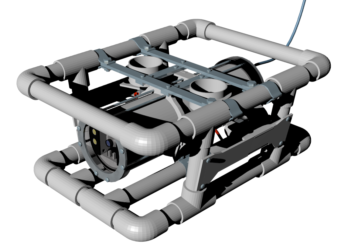
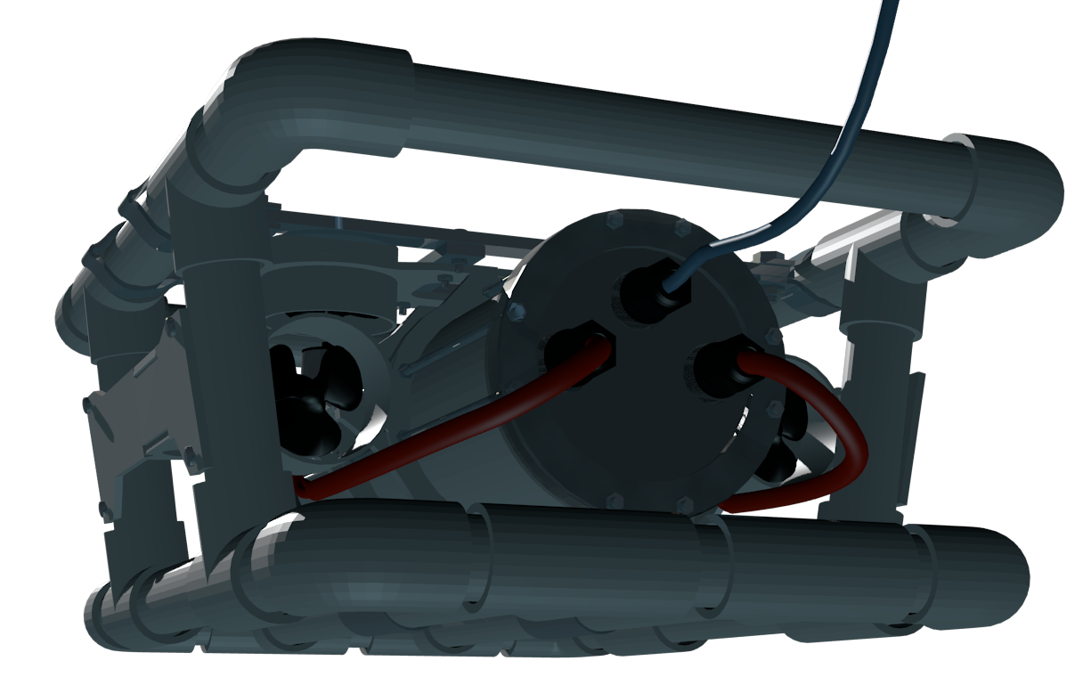
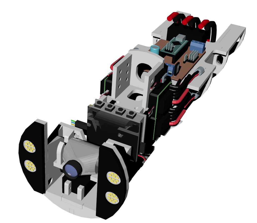
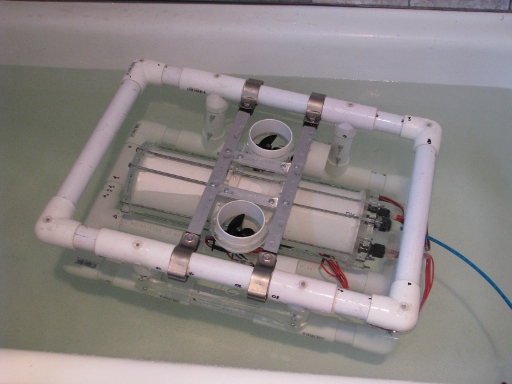
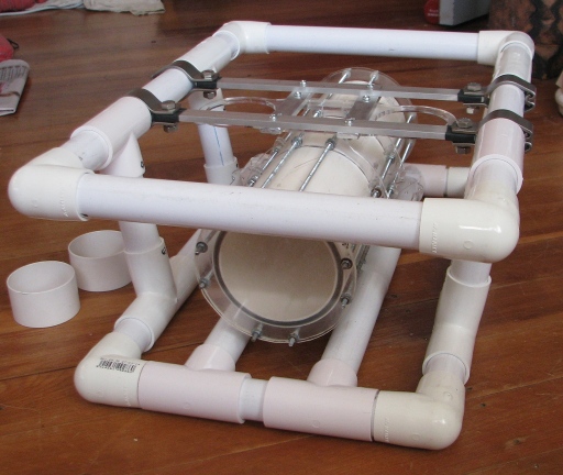
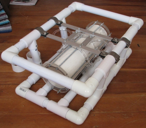
Current Design using uPVC pressure pipe.
Current Design Internal Structure.
The Blender design files can be found here - ROV-Devt-Current_Version-blend.zip.
If you are looking for 1:1 scale digital models of the commercial components used in this project you will be able to find most of them in Blender and OBJ formats on the Component Model Library Page
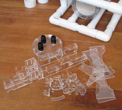
Panels
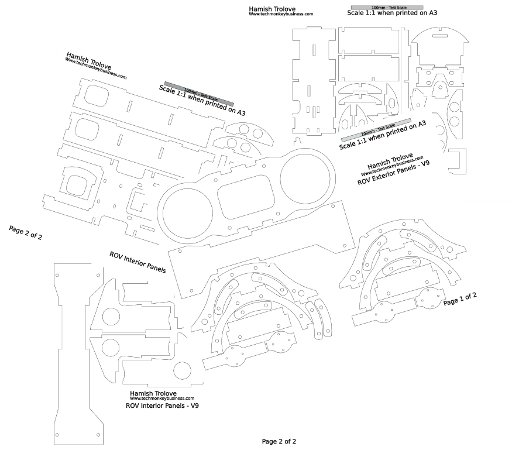
The panels supporting the outer frame (25mmNB uPVC Pressure Pipe) are designed to be laser cut from 4mm thick acrylic. At this stage the files are provided as a 1:1 pdf that can be printed on A3 paper for transfer to the plastic sheet and as a dxf that can be used to lasercut the panels from a 600mm square sheet.
The Panel Plans are provided in a number of other vectorgraphic formats. The original drawing was done in TurboCAD so the dimensions in that file are correct. The formats available are TurboCAD, DGN, DXF and DWG. The TurboCAD file is the correct scale and inspection of the others suggests they are all correct too although some distortion is present in the top plate for holding the vertical thruster ducts. You can download this file from here - ROV-Devt-Current_Version_panels.zip.
A pdf of the exterior and interior panels is available here. The drawings are all 1:1 scale and designed to be printed on A3. Make sure any automatic scaling is turned off before you send the file to the printer and check the print out scale is correct with the 100mm check box at the bottom of each page.
The Lasercutting dxf file can be found here - ROV-Devt-Current_Version_panels-lasercut.zip
Tether Management System
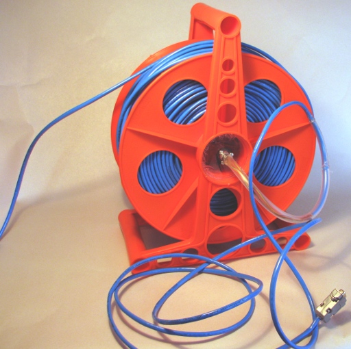
The Tether Management System for the ROV went together remarkably well, and I feel I ended up with a good robust system that will be able to withstand the rigours of operating in a marine environment. Here is a description of the kit used.
ROV Manufactures
While travelling in Canada serendipity was on my side and I found some ROV manufacturers to go and visit. Here are some notes from those visits.
Trials
Now that the ROV is more or less complete I have begun some trials.
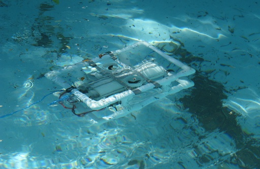
Some Piccies
The following pictures are just to prove that the project is real and that I am not simply mucking about playing with Arduino Code and making pretty digital models on my computer….. although I do that a bit too.
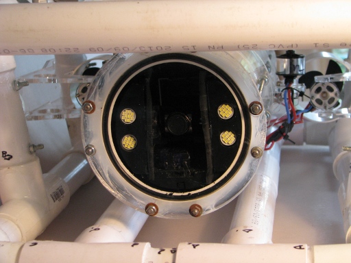
ROV Front end with electroncs pod in place - and lens cap still on.
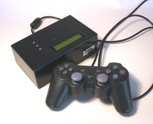
The Topside Box and Controller.
Here are a couple of photos of the structure now that I have the lasercut acrylic parts to hand. And hey! It even looks like the rendered digital model.
The parts shown below are the lasercut acrylic internal structure. This will be painted matt black in due course.
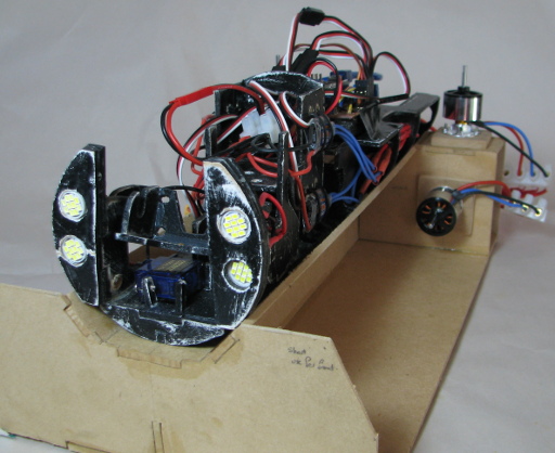
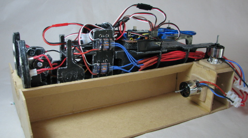
In the pictures below the ROV interior is sitting on a test rig so that I can get the motors coordinated without them buzzing around all over the place as they would if I did not have them mounted on anything. The interior panels in this development version are all hand cut black painted MDF carefully buffed down to give that aged chipped paint look. In the end product the panels are clear acrylic with a black metal primer paint and look alot swisher.
The choice of black is to give the impression of sophistication and stylishness while reducing the internal reflection that may interfere with the view from the ROV when in the dark depths. The camera is not installed at this time to save it getting knocked around but the cradle can be seen between the light arrays. The electronics circuit board is simply taped in place.
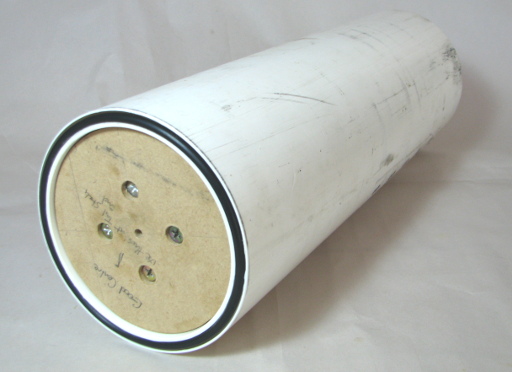
Below is an image of the main ROV shell with the seals installed and the centering core that I used to hold the shell in my lathe so that I could face off the ends and cut the seal glands.

ROV presented here by Hamish Trolove is licensed under a Creative Commons Attribution-NonCommercial-ShareAlike 4.0 International License.