Control of the Horyzon HD Camera with an Arduino
The ROV makes use of a HoryzonHD Full HD 1080p FPV camera V3 sold by FoxtechFPV for the pilot’s view of the world and also to record or take photos. Because it is sealed in the ROV it is going to need to be controlled remotely via the ROV’s Arduino.
The triggers on the HoryzonHD are a couple of easily accessed ports, one to trigger photos and the other to toggle between recording video and stopped. On the camera I have to hand the ports are labeled around the wrong way both on the camera case and in the supplied information sheet. Hopefully they have fixed this in the V4 version that has been released as of Jan 2015. The camera trigger wire colours in the supplied JST connector are: Red = Video, White = Photo.
In order to trigger an event the trigger port voltage needs to be dropped to ground.
So without further ado, here is the circuit. Click on the image if you would like a higher resolution version.
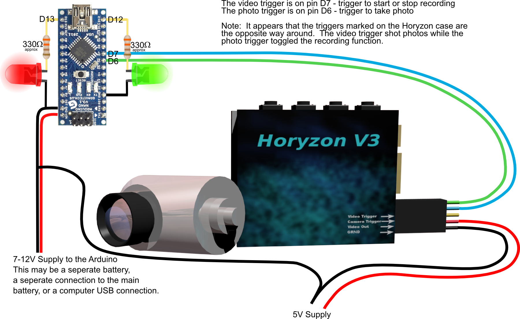
The two LEDs are status flags to indicated if the camera is recording or not or whether a photo event has been triggered.
When installed in the ROV the yellow Video out line goes to the baluns and into the CAT5 tether as described in this [page](](/articles/Video_over_CAT5.html).
The following is the sketch to run a sequence of five photos followed by recording 15 seconds of video and then a couple more photos. Needless to say you will need a MicroSD card in the camera for this to work properly.
Because the controls for the Boscam Cobra HD camera are basically the same as for the FoxtechFPV HoryzonHD Camera it is likely that this sketch and the circuit will work just as well for that camera.
The sketch below can be downloaded from here: HoryzonTrigger.ino
#The Arduino Sketch
/*
HoryzonTrigger.ino
The Horyzon V3 Full HD FPV camera that may be used in the ROV
has some ports for remote triggering of the video record and photo
functions.  This sketch is intended to activate those using an
Arduino.  The Horyzon camera is supplied with 5V from a Turnigy
UBEC.  In the ROV this camera will be supplied via the ESC BEC
supply through a nice big capacitor.

The triggers for the camera are achieved by dropping the ports to
ground.  We will do this by maintaining the pins as HIGH, and then
changing them to LOW whenever a photo is to be taken or the video
recording to start or stop.

The video trigger is on pin D7 - trigger to start or stop recording
The photo trigger is on pin D6 - trigger to take photo

A green LED is on pin D12 - this will be lit when a photo is taken
A red LED is on pin D13 - this will be lit when a video is recording

Note:  The illustration in the Horyzon V3 instruction manual is
incorrect as are the markings on the Casing.  The video trigger is
on the RED WIRE in the JST connector, and the phototrigger is on the WHITE
WIRE in the JST connector.


*/

const int redLEDpin = 13;  //The red LED is on pin D13
const int grnLEDpin = 12;  //The green LED is on pin D12
const int vidtrigpin = 7;  //The video trigger is on pin D7 connects to Red wire in JST
const int photrigpin = 6;  //The photo trigger is on pin D6 connects to White wire in JST

void setup()
{
  //initialise all of the pins to be used.
  pinMode(redLEDpin, OUTPUT);
  pinMode(grnLEDpin, OUTPUT);
  pinMode(vidtrigpin, OUTPUT);
  pinMode(photrigpin, OUTPUT);

  // The default state for all pins is HIGH.  To trigger the
  // camera function momentarily put the pin to LOW.

   digitalWrite(vidtrigpin, HIGH);
   digitalWrite(photrigpin, HIGH);

  //To keep this simple the video and photos will be triggered in
  // a sequence set up below rather than introduce buttons and
  // other things that can add complication through button bounce
  // etc.

  //Take five photos
  for(int pics = 1; pics < 6; pics++)
  {
    delay(5000); //five second delay from the start of the sketch
    digitalWrite(photrigpin, LOW); //trigger the photo pin
    digitalWrite(grnLEDpin,HIGH);  //light the green LED pin
    delay(200); //hold this state for 200milliseconds.
    digitalWrite(photrigpin, HIGH); //reset the photo trigger pin
    digitalWrite(grnLEDpin,LOW);  //turn off the green LED pin
  }
  delay(10000); // delay ten seconds
  digitalWrite(vidtrigpin,LOW);  //Start recording video
  digitalWrite(redLEDpin,HIGH);  //Show recording status is on
  delay(200); //hold the trigger signal.
  digitalWrite(vidtrigpin,HIGH);  //reset the trigger
  delay(15000); //Continue recording for 15 seconds.
  digitalWrite(vidtrigpin,LOW);  //Stop recording video
  digitalWrite(redLEDpin,LOW);  //Show recording as having finished
  delay(200); //hold the trigger signal.
  digitalWrite(vidtrigpin,HIGH);  //reset the trigger

  //Take two more photos
  for(int pics = 1; pics < 3; pics++)
  {
    delay(5000); //five second delay from the start of the sketch
    digitalWrite(photrigpin, LOW); //trigger the photo pin
    digitalWrite(grnLEDpin,HIGH);  //light the green LED pin
    delay(200); //hold this state for 200milliseconds.
    digitalWrite(photrigpin, HIGH); //reset the photo trigger pin
    digitalWrite(grnLEDpin,LOW);  //turn off the green LED pin
  }

}

void loop()
{
  // To indicate that the Arduino thinks the sequence is finished
  // the two LED will be flashed.

  digitalWrite(redLEDpin, HIGH);   // set the red LED on
  digitalWrite(grnLEDpin, HIGH);   // set the green LED on
  delay(1000);              // wait for a second
  digitalWrite(redLEDpin, LOW);    // set the red LED off
  digitalWrite(grnLEDpin, LOW);   // set the green LED off
  delay(1000);              // wait for a second
}