A Simple Arduino Based Logger

This article describes a simple Arduino based logger for capturing temperature data and recording it to a MicroSD card. The logger is made very simple by not using a Real Time Clock, but rather just counting seconds elapsed since the device was turned on. After all for the purpose of this logger we don’t really need to know that it is Tuesday the 19th of January 2016 11:49:23. All we really need is that the temperature is 22°C 75 seconds after we started the experiment.
The project is a stepping stone towards a logger for running some pressure tests on the ROV shell. The local Dive company, New Zealand Diving and Salvage have very kindly offered me use of their decompression chamber to pressure test the ROV, or as they described it, “give it a squeeze.” This means I will be able to simulate the 50m depth that the ROV is rated to without killing it if it fails. The challenge is that if it leaks it will not be full of water and so it will be hard to tell if it failed. This is why I am developing this logger. This will sit in the ROV shell and record the pressure and temperature inside while the ROV is held at the design pressure for a period. If the pressure rises then there is a problem. The logger described in this article will have a barometric pressure sensor (BMP180 – this incorporates a temperature sensor) and depth sensor (MS5803-14BA) added for the pressure test as well as a 4 digit display to show the internal pressure. The updated logger is described in this article.
The logger described here makes use of a Seeeduino Stalker. It is a bit nasty to use owing to it being configured for very efficient standalone operation on batteries and having some of its ports allocated to inbuilt components such as a Real Time Clock, MicroSD Card socket, and various other features that optimise it for use as a logger. The project described here can be used with any other Arduino, but may need to make two changes to the sketch:
- You may need to adjust the pin assignments for the MicroSD Card shield or breakout board you use.
- You will probably need to change the “
.003222657” factor in thegetVoltagesubroutine to “.004882814” if you are using a typical Arduino with a 5V reference voltage for the Analog Pins.
The Circuit
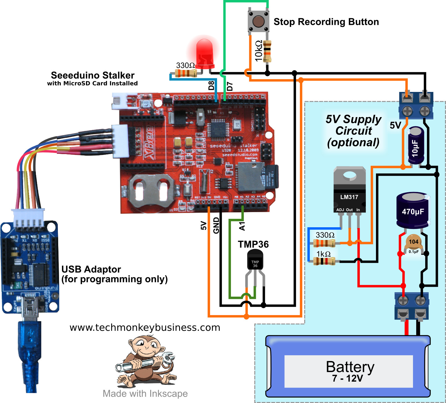
Diagram of the connections for the simple logger. Click on the image for a hi-res version.
The diagram here includes an optional LM317 based regulated supply to provide 5V to the Arduino and sensors from a battery should a standalone logger be required. The system is not optimised to minimise battery consumption so if you are looking to produce an Arduino based logger that can be put out in the field and run on batteries for an extended period, then I would suggest looking in the book “Arduino Projects to Save the World” by Emergy Premeaux and Brian Evans (ISBN978-1-4302-3623-8) which describes in great detail how to set up an efficient logger with minimal energy consumption and capable of running on Solar Power.
Both the push button to stop logging and the TMP36 temperature sensor require 5V to operate.
Things you may want to fiddle with
The period between readings is 5 seconds. You can change this to any other time by changing the figure in the line that looks like this;
int RdgDelay = 5000;
The output file is called PSLog.csv. This can be changed in the line:
LogFile = SD.open("PSLog.csv",FILE_WRITE);
What it does
The sketch is controlled by the ProcessRun flag. It will keep on logging to the file it has created until the button is pushed which will set the ProcessRun flag to “false” and close the file. Once that is done it jumps to the Blink() subroutine which, because of the while(1) statement, remains caught in that loop indefinitely until the Arduino is switched off.
As far as writing data to the MicroSD Card goes this is handled by assembling a string from the variables being recorded and writing that to the SDCard. The lines for doing this are these ones;
dataString = String(timestamp) + "," + String(int(temperature));
LogFile.println(dataString);
Using the millis() function to keep track of the elapsed time between readings allows the sketch to run smoothly and efficiently. When the elapsed time since the Arduino was turned on exceeds the stored elapsed time of the last reading (RdgTime) plus the time between readings (RdgDelay), a new reading is taken and the elapsed time of the last reading (RdgTime) is updated.
The Sketch
The code can be downloaded from here: SimpleLoggerv1.ino
/*
SimpleLoggerv1.ino
By Hamish Trolove
www.techmonkeybusiness.com
This is a sketch designed to run on a Seeeduino Stalker.
It will measure and log a TMP36 temperature sensor.
This sketch is designed to form the basis for a pressure and
temperature logger for testing the ROV capsules seals at a simulated
depth. Although the Seeeduino Stalker includes an onboard
Real-Time_Clock we will just record time since starting the
Arduino rather than time of day.
The onboard MicroSD card will be used.

Please note that the Seeeduino Stalker uses a 3.3V reference
rather than the usual 5V and so the temperature measurement
expression from the TMP36 sensor will need modification.
This is described in the inline comments below.

A button will be used to stop logging.

Power supply is 9.9V from a 3S LiFePO4 battery through Vin.

Pin Assignments

The connections are:
5v supply to the TMP36 (the 3.3V supply will not yield any output)
Ground to the TMP36
middle pin of the TMP36 to Analogue Pin A1 on the Arduino.

D10 is for the SD Card Chip Select
D12 and D13 are used by the SD Card

D7 has a button attached for stopping the logger
D8 makes use of the on-board LED.


The file created is a .csv format.  If for some reason the sketch
stops and then starts again, the new data is appended.  The old
data is not overwritten. Just make sure the button is used to stop
it so that the file can be closed.


*/


#include <SD.h>      //SD Card Library
#include <Wire.h>

// Note that even if it's not used as the CS pin, the hardware
// CS pin (10 on most Arduino boards),must be left as an output
// or the SD library functions will not work.  In the Seeeduino
//Stalker the CS is on Pin 10.

const int chipSelect = 10;  //SD Card Connection
const int StopPin = 7;    //Stop the process pin.
const int LEDPin = 8;     //On Board LED.

const int temperaturePin = A1; //TMP36 is connected to analogue pin A1
                         //the resolution is 10 mV / degree celcius
float temperature = 0;
boolean ProcessRun = true; //Toggle to run the process until button pushed.

String dataString = "";  // make a string for assembling the data to log:
int timestamp = 0;     //The is the seconds since starting the process.
File LogFile; //The file object we will log to.

int RdgDelay = 5000;  //5 seconds between readings
unsigned long RdgTime = 0; //Time of last reading.


void setup()
{
  delay(5000); //The usual 5 second delay
  Wire.begin();
  Serial.begin(9600);
  pinMode(chipSelect, OUTPUT);  //Make sure default chip select is set to output.
  pinMode(StopPin,INPUT);
  pinMode(LEDPin,OUTPUT);
  //SD.begin(chipSelect);
  if (!SD.begin(chipSelect))
  {
    Serial.println("initialization failed!");
    return;
  }
  LogFile = SD.open("PSLog.csv",FILE_WRITE);  //Open the file to log data to.
}

void loop()
{
  Serial.println("Running");
  while(ProcessRun)
  {
    if(digitalRead(StopPin)==HIGH)
    {
      LogFile.close();  //If the button is pressed close the file.
      ProcessRun = false;
      Serial.println("Stopping");
      Blink();
    }

    if(millis() > RdgTime+RdgDelay)
    {
       //Take reading and write to file.
      RdgTime = millis(); //Capture the time readings start.

      float temperature = getVoltage(temperaturePin);
        //getting the voltage reading from the temperature sensor
      temperature = (temperature - .5) * 100;
        //converting from 10 mv per degree with 500 mV offset.

      //Generate the time stamp
      timestamp = RdgTime/1000; //Time since start in seconds.

      dataString = String(timestamp) + "," + String(int(temperature));
      LogFile.println(dataString);
      Serial.println(dataString);

    }
  }


}


/*
The getVoltage() subroutine - returns the voltage on the analog
input pin for the TMP36
*/
float getVoltage(int pin)
{
  return (analogRead(pin) * .003222657);//converting from a 0
    //to 1024 digital range to 0 to 3.3 volts (each 1 reading equals
    //~ 3 millivolts.  Note that this is different for a Stalker
    //because of the 3.3V reference rather than the usual 5V reference.

    //For a 5V reference use the factor .004882814 instead.
}

void Blink()
{
  while(1)
  {
    digitalWrite(LEDPin,HIGH);
    delay(500);
    digitalWrite(LEDPin,LOW);
    delay(500);
  }
}