Three Arduino Circuits for Temperature Measurement

While busy designing the programs for the ROV, it suddenly struck me that having a temperature sensor within the housing would be useful to provide some feedback if things were starting to go pear-shaped down there. After all if it gets too hot down there, the shell integrity will be compromised.
What I wanted was something simple that would be relatively responsive and not too memory intensive. There were three sensors that I knew of that fitted that description.
- Thermistors.
- DS18B20 One-wire temperature sensors.
- TMP36 temperature sensor.
So I sat down and connected up each type of sensor to an Arduino Uno with a Freetronics style LCD button shield attached to do a rough comparison of each type. When I say “rough” I mean “Does it give me a reasonable answer in a reasonable time” rather than comparing how many milli-Kelvin difference each has when immersed in a triple point calibration bath. I am also a simple soul so simple and easy to follow coding also gets good marks in my book.
The keypad LCD display shield used for output makes use of the LiquidCrystal.h library which is part of the Arduino IDE so you should not need to go hunting for extra libraries in order to get these sketches working.
Thermistors
I guess the simplest in terms of technology is the thermistor. It is a variable resistor where the resistance changes with temperature. By building a voltage divider for it you can get a reasonably accurate temperature measurement with relative ease. For my experiment I had to hand a bunch of 10kΩ NTC thermistors – they have 10kΩ resistance at 25°C (298.15K). This meant that the other resistor in the voltage divider should be 10kΩ.
So here is the circuit.

The only connections to the Arduino via the LCD shield are the 5V supply to the thermistor, the common point between the resistor and the thermistor connected to the analogue A1 port on the Arduino/LCD shield, and finally, the ground of the Arduino/LCD shield connected to the end of the 10kΩ resistor.
The real challenge with thermistors is that the relationship between the voltage detected by the Arduino Analogue pin is not linear with temperature. Wikipedia has a good page on this. https://en.wikipedia.org/wiki/Thermistor
Luckily I am dealing with an NTC thermistor which has a somewhat simpler temperature relationship expression called the “B or β parameter equation”. For my Thermistor’s I looked up the Beta Value on the suppliers website and found that it was 4100.
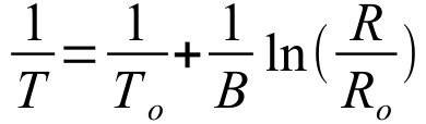
So the relationship between resistance and temperature can be written as shown below.
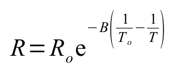
or
The variables are:
R = the resistance at the temperature you are measuring (Ω)
Ro = resistance quoted for the resistance at the reference temperature. In this case 10000Ω at 298K
T = temperature you are measuring (K)
To = reference temperature at which the resistance Ro is quoted for. In this case 298.15K.
B = the beta value.
Applying ohms law to the voltage divider and knowing that the reading that the Arduino takes will be a value between 0 and 1023, I came up with the following relationship to use in the Arduino program.

Here Data is the raw reading from the Arduino analogRead function. The temperature output from this expression is still in Kelvin.
The Thermistor sketch below can be downloaded from here: Thermistorv1.ino
Here’s the code:
/*
Thermistorv1.ino
Hamish Trolove - 26 Jan 2015
www.techmonkeybusiness.com
This is a thermistor trial to find an efficient way of monitoring
the temperature within the ROV.  There is plenty of space on the
Analogue pins for a Thermister voltage divider.

I have to hand a 10kohm NTC Thermistor with a Beta value of 4100.

OK.  Real simple circuit.  Output will be an LCD shield.

5v is supplied to the voltage divider
voltage divider is connected to the A1 pin on the Arduino
the 10kohm resistor is connected to the ground.

*/

#include <LiquidCrystal.h>
#include <math.h>
#define LCD_BACKLIGHT_PIN 10  // D10 controls LCD backlight
const int ThermPin = A1;  // The thermistor is on Analogue Pin 1
double ThermValue = 0; // Somewhere to stick the raw Analogue Pin Value.

LiquidCrystal lcd( 8, 9, 4, 5, 6, 7 );   //Pins for the freetronics
    //16x2 LCD shield.
    // While this particular display has some buttons as well we will
    // not bother to use them.


void setup()
{
  digitalWrite( LCD_BACKLIGHT_PIN, HIGH );
  // set up the LCD's number of columns and rows:
  lcd.begin(16, 2);
  // Print a message to the LCD.
  lcd.print("Temperature degC");
}

void loop()
{
  ThermValue = analogRead(ThermPin);  //What is the raw value from the
                                      //Voltage Divider?
  double TempVal = 1/((1/298.00)+(1/4100.00)*log(1024.00/ThermValue-1.00));
  TempVal = TempVal - 273.00;  //Note the extra decimal places force float usage.
  // set the cursor to column 0, line 1
  // (note: line 1 is the second row, since counting begins with 0):
  lcd.setCursor(0, 1);
  // print the number of seconds since reset:
  lcd.print(TempVal);
  delay(500);
}
It ends up being a nice simple and very logical sketch which is great by my books. The only downside is that it requires the use of the math.h library which takes up a tiny bit of extra room, but not so much to be a problem, and math.h is within the Arduino IDE anyway. The memory used for this sketch was 4720 bytes.
The thermistor is quick to respond to changes in temperature and is good up to 125°C. If the interior of the ROV gets up to 125°C, it will be game over anyway.
Thermistors are cheap at $1.90 each here in New Zealand.
DS18B20 One-wire temperature sensors
The DS18B20 is a pretty smart piece of kit that can identify itself uniquely to the master (the Arduino in this case) and provide highly accurate temperature measurements that are very responsive. The real bonus is that because of their ability to uniquely identify themselves you can put several of them on the same Arduino pin. The downside is that they need a new library that does not ship with the Arduino IDE. The OneWire library can be found with this link – http://www.pjrc.com/teensy/arduino_libraries/OneWire.zip. Also the code is a bit inscrutable.
Here is the circuit.
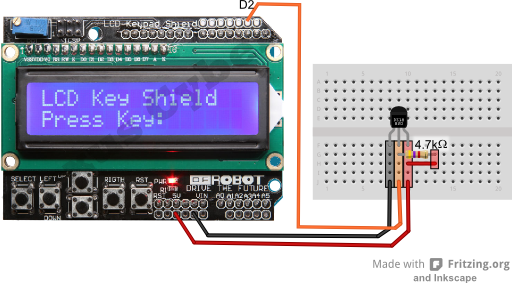
In this configuration the DS18B20 is operating in its normal power mode rather than the parasitic power mode where it draws it’s power from the Arduino digital pin.
Anyway, the code that I have presented below is a drastically paired down thing from one of the original examples provided with the library. I have added coding to accommodate the LCD Button shield so that the Arduino can report via that rather than the Serial Monitor. Once I had chopped off the unnecessary bits of code (because we know what sort of chip we’re using and we know that it works), the code was somewhat shorter but because it uses bits and bytes for communicating it is still inscrutable. So please don’t ask me how it works. I have no idea.
I have since found some better examples of more comprehensible coding for these sensors on the web. If you like the DS18B20 sensor way of doing things then I would recommend you look at the tutorial on the hacktronics website http://www.hacktronics.com/Tutorials/arduino-1-wire-tutorial.html. It is well written and makes good sense …. not that I could get their method to work with the DS18B20 address identified using their address identifier sketch. Ah well. Never mind. Maybe DS18B20s are not for me.
Anyway, here is my sketch. It works but dealing with bytes is a bit beyond my poor little brain to comprehend. You can download the sketch from here if you would prefer: DS18B20_to_LCD_Example.ino
The sketch calls on the OneWire library. This can found on this website http://www.pjrc.com/teensy/arduino_libraries/OneWire.zip or from the following webpage: A Collection of Arduino Libraries Used in This Project.
/*
DS18B20_to_LCD_Example.ino
Hamish Trolove - 26 Jan 2015
www.techmonkeybusiness.com
This example sketch was based on the one that shipped with
the OneWire library.  It has been heavily modified to look at
only one sensor and that sensor is a DS18B20.  The data is reported
to an LCD screen shield of the Freetronics configuration.

With the shield on the Arduino, the extra connections for the
DS18B20 are a 5V supply, a connection between the middle leg of the
sensor and Arduino pin D2, as well as the ground.  A 4.7kohm resistor
is between the 5V line and the middle leg of the sensor.  So in this
case the sensor is operating in Normal Power Mode which means the
whole system can run a bit quicker.

*/

#include <OneWire.h>
#include <LiquidCrystal.h>
#define LCD_BACKLIGHT_PIN 10  // D10 controls LCD backlight
LiquidCrystal lcd( 8, 9, 4, 5, 6, 7 );   //Pins for the freetronics
    //16x2 LCD shield.
    // While this particular display has some buttons as well we will
    // not bother to use them.


OneWire  ds(2);  // on pin 2 (a 4.7K resistor is necessary)

void setup(void) {
  digitalWrite( LCD_BACKLIGHT_PIN, HIGH );
    // set up the LCD's number of columns and rows:
  lcd.begin(16, 2);

}

void loop(void) {
  byte i;
  byte present = 0;
  byte type_s;
  byte data[12];
  byte addr[8];
  float celsius, fahrenheit;
  // set the cursor to column 0, line 0
  lcd.setCursor(0, 0);
  ds.search(addr);

  ds.reset();
  ds.select(addr);
  ds.write(0x44, 0);        // start conversion, with power supplied from 5V rail

  delay(100);

  present = ds.reset();
  ds.select(addr);
  ds.write(0xBE);         // Read Scratchpad

  for ( i = 0; i < 9; i++)
  {           // we need 9 bytes
    data[i] = ds.read();
  }


  // Convert the data to actual temperature
  // because the result is a 16 bit signed integer, it should
  // be stored in an "int16_t" type.
  int16_t raw = (data[1] << 8) | data[0];
  byte cfg = (data[4] & 0x60);
    // at lower res, the low bits are undefined, so let's zero them
  if (cfg == 0x00) raw = raw & ~7;  // 9 bit resolution, 93.75 ms
  else if (cfg == 0x20) raw = raw & ~3; // 10 bit res, 187.5 ms
  else if (cfg == 0x40) raw = raw & ~1; // 11 bit res, 375 ms
    //// default is 12 bit resolution, 750 ms conversion time

  celsius = (float)raw / 16.0;

  lcd.print(celsius);

}
In my opinion, the DS18B20 is great for monitoring complex networks of temperature sensors. They are fast, and accurate, but for my needs the code I have used is difficult to follow, and the circuit is no simpler than the thermistor circuit if you are only dealing with one sensor. The sketch took 5318 bytes of memory which is not all that bad. I have not retried my example using the more logical and easy to follow coding used in the Hacktronics tutorial so I can’t comment on the relative use of memory for this alternative scheme.
Here in New Zealand the price to buy one is $11.61 NZD from element14 which is the usual outrageous rip-off that happens here. I say this because it is easy to get some comparable prices from elsewhere in the world. The DS18B20s are $4.25 USD each from Sparkfun, or $5.50 AUD each from element14 in Australia.
TMP36 temperature sensor
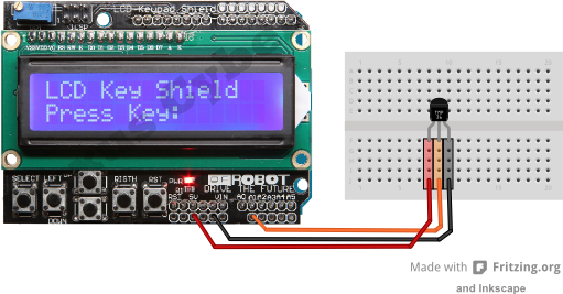
I had a bunch of sensors and things in my Starter Kit including the TMP36 Precision Temperature Sensor. This looks like a transistor and is very simple of connect to the Arduino. One leg goes to the 5V pin, the middle pin to an Arduino Analogue pin and, the other leg to the Arduino’s ground. There are no extra resistors to add.
Here is the circuit. Simple eh?
The TMP36 provides a voltage on its middle leg that varies linearly with temperature. The relationship is 10 millivolts per degree Celsius and it includes an offset of 500mV to allow it to measure temperatures below 0°C. To read this hardware and to turn it into meaningful temperature values does not require any additional libraries or complex mathematical expressions.
The code for the TMP36 was developed from the Arduino Experimentation Kit example CIRC-10, the only real changes being to change it to report through the LCD Button shield rather than the Serial monitor.
The code presented below can be downloaded from here if you would prefer: TMP36_Temperature_Sensor.ino
/*
TMP36_Temperature_Sensor.ino
Hamish Trolove - 26 Jan 2015
www.techmonkeybusiness.com
This sketch uses the TMP36 sensor and is based on
the Arduino Experimentation Kit example CIRC-10.
It has been modified to report through the Freetronics
clone LCD button display shield.

The connections are:
5v supply to the TMP36
Ground to the TMP36
middle pin of the TMP36 to Analogue Pin A1 on the Arduino.

*/


#include <LiquidCrystal.h>
#define LCD_BACKLIGHT_PIN 10  // D10 controls LCD backlight

const int temperaturePin = A1; //TMP36 is connected to analogue pin A1
//the resolution is 10 mV / degree celcius

LiquidCrystal lcd( 8, 9, 4, 5, 6, 7 );   //Pins for the freetronics
    //16x2 LCD shield.
    // While this particular display has some buttons as well we will
    // not bother to use them.

void setup()
{
  digitalWrite( LCD_BACKLIGHT_PIN, HIGH );
  // set up the LCD's number of columns and rows:
  lcd.begin(16, 2);
}

void loop()
{
  float temperature = getVoltage(temperaturePin);
    //getting the voltage reading from the
    //temperature sensor
  temperature = (temperature - .5) * 100;//converting from 10 mv
    //per degree with 500 mV offset.
  lcd.setCursor(0, 0);
  lcd.print(temperature); //printing the result
  delay(100);
}

/*
getVoltage() - returns the voltage on the analog input
defined by pin
*/

float getVoltage(int pin)
{
  return (analogRead(pin) * .004882814);//converting from a 0
    //to 1024 digital range to 0 to 5 volts (each 1 reading equals
    //~ 5 millivolts
}
The TMP36 is simple to connect and also quite memory efficient seeing as the sketch above only used 4294 bytes of memory. It appeared that the response to temperature changes was somewhat slower than the thermistor or the DS18B20, but I was hardly very scientific about testing that anyway. The coding is quite simple too. On the whole the TMP36 was well suited to the needs of the ROV project.
The TMP36 is also cheap, even here in New Zealand. They sell for about $2.94 NZD each.
Summary
So you’ve read your way down this far. I guess you want a summary table now too. Alright then, here is a summary table. It is not all that scientific and is really just a few of my observations and opinions.
|
|
Thermistors |
DS18B20 |
TMP36 |
|
Analogue or digital |
Analogue |
Digital |
Analogue |
|
Easy of circuit. |
Quite easy |
Quite easy |
Very easy |
|
Extra Libraries to include in code. |
Math.h (built into the Arduino IDE anyway) |
OneWire – this library needs to be added. |
None. |
|
Coding complexity (for simple people like me) |
Reasonably logical |
Incomprehensible |
Simple |
|
Response to temperature changes |
quick |
Very quick |
Not so quick |
|
Amount of memory needed compared to each other. |
4720 bytes |
5318 bytes |
4294 bytes |
|
Cost (in New Zealand) |
Cheap |
Rip-off |
Cheap |
|
Suitability for the ROV Project |
Well suited |
It's good but the other options are probably better for this application. |
Well suited |