A Simple Pressure and Temperature Logger

The local Dive company, New Zealand Diving and Salvage have very kindly offered me use of their decompression chamber to pressure test the ROV. This means I will be able to test the ROV shell and seals subjected to the 50m design depth that the ROV is rated to without killing it if it fails. The challenge is that if it leaks it will not be full of water and so it will be hard to tell if it failed. To show up the presence of leaks I have developed this simple pressure and temperature logger which will be installed inside the ROV shell in place of the control electronics. This will record the temperature and pressure inside the shell while the ROV is held at the design pressure for a period. If the pressure rises then there is a problem. This experiment has been run now, and you can read about it here:Pressure Testing the ROV.
This article describes an upgraded logger arrangement that measures pressure and temperature from two pressure sensors; a BMP180 barometer for when things go right, and an MS5803-14BA high pressure sensor for when things go wrong. A TM1637 4-digit display (http://www.techmonkeybusiness.com/tm1637-4-digit-display-example-sketch.html) is also included to provide immediate feedback to me about the pressure inside the shell.
Unlike the previous simple logger I described in an earlier article this logger is based on the fabulous Arduino Nano. This means that the circuits and sketches presented here will work on the common Arduinos. An SD Card module is used to record the measurements. The SD Card module I used is this one from www.dx.com (SKU-205308). It works with the standard SD library that comes with the Arduino IDE, and uses the SPI connections on pins D11 through to D13 (as they are on the Arduino Nano) with the Chip Select assigned to D10.
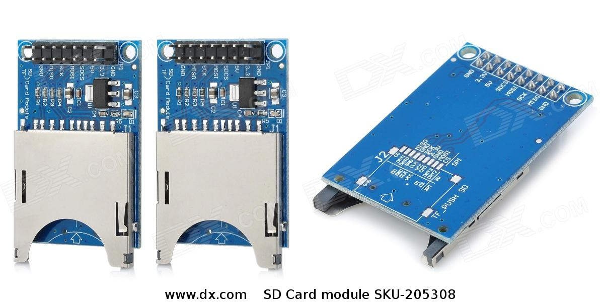
The SD Card module used in this project. Click on the image for a larger image.
This logger does not have a real time clock and so is only recording the elapsed time since the sketch starts running. For loggers designed to collect data over longer periods a real time clock will be needed along with all the extra processing that entails.
The data being logged to the SD card at five second intervals is in a .CSV format and looks like this;
125, 1022 , 24.32 , 102183 , 24.33
130, 1022 , 24.31 , 102184 , 24.32
135, 1022 , 24.31 , 102186 , 24.33
140, 1022 , 24.30 , 102182 , 24.32
Where the first column is the time in seconds since the logger started recording, the second and third columns are the pressure and temperature from the MS5803-14BA high pressure sensor and the remaining two columns are the pressure and temperature from the BMP180 barometric pressure sensor.
The Circuit
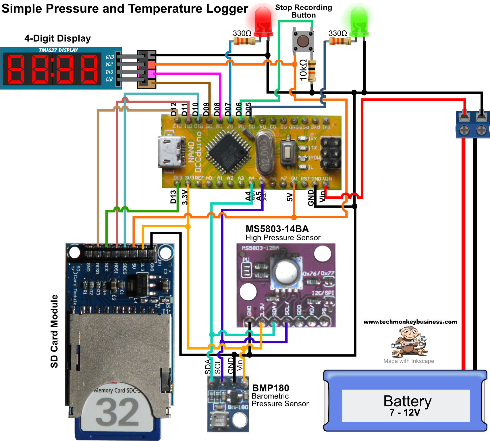
Click on the image for a larger image.
The Arduino Nano is being supplied by a 9.9V LiFePO4 battery in this project but could be supplied from any source between 7V and 12V. Because none of the modules attached to the Arduino require much power, they are being supplied from the Arduino 3.3v and 5V pins. It is worth pointing out that the SD Card used here requires both the 5V supply and the 3.3V supply to be connected to work. I’d also like to point out that the card installed in the SD Card module is not 32Gb but rather a very old 32Mb one that shipped with my digital camera (32Mb? How many shots is that?) - even 32Mb is overkill for the amount of data being collected.
A button is installed to stop the logger and close the file on the SD Card. No provision has been made to restart the logger other than hitting the reset button on the Arduino.
The two LEDs indicate when it is logging and when it has been stopped.
Connections the the Arduino
The connections are shown on the diagram above and described in the sketch, but for the sake of clarity here is the list.
Pin Assignments are:
D06 has a button attached for stopping the logger.
D07 is for a red indicator LED.
D05 is for a green indicator LED.
SD Card Module
D10 is for the SD Card Chip Select.
D11 is for the SD Card MOSI.
D12 is for the SD Card MISO.
D13 is for the SD Card SCK.
The SD Card board needs to be supplied with both 3.3V and 5V.
TM1637 4-Digit Display
A 5V and ground connection are supplied to the 4-Digit display.
D8 goes to the 4-digit display DIO pin.
D9 goes to the 4-digit display CLK pin.
I2C Pressure Sensors
GND pins on MS5803-14BA and BMP180 sensors to Nano GND pin.
Vcc pins on MS5803-14BA and BMP180 sensors to Nano 3.3V pin.
SDA pins on MS5803-14BA and BMP180 sensors to Nano A4 pin.
SCL pins on MS5803-14BA and BMP180 sensors to Nano A5 pin.
Both MS5803-14BA and BMP180 sensors are on breakout boards with all necessary resistors capacitors to protect them.
Both sensors communicate using I2C and so must be attached to the A4 and A5 pins of the Arduino Nano (Mega’s have a little more choice about this). I originally tried “daisy-chaining” the SDA and SCL connections between the two sensors and the Arduino on the breadboard but found this was unreliable. To guarantee the data would get through efficiently I wired both sensors directly back to the Arduino instead.
Luckily both sensors use different addresses by default and so there were no challenges around conflicts. The MS5803-14BA high pressure sensor uses I2C communication Address 0x76 and the BMP180 barometric pressure sensor uses I2C communication Address 0x77.
The Sketch
The code can be downloaded from here: PTLoggerv4.ino
The sketch calls on a number of Third Party libraries. The sources for these are noted in the sketch, but you can find them from this page if you would prefer. The libraries used are;
- Avishorp’s TM1637 4-digit display library https://github.com/avishorp/TM1637.
- The MS5803_14 library from Luke Miller http://github.com/millerlp
- The BMP180 library from Love Electronics Ltd (loveelectronics.com) http://embedded-lab.com/blog/bmp180/bmp180_11/
/*
PTLoggerv4.ino
By Hamish Trolove
www.techmonkeybusiness.com
This is a sketch designed to run on an Arduino Nano with the following
sensors attached.

MS5803-14BA high pressure sensor (I2C communication Address 0x76)
BMP180 barometric pressure sensor (I2C communication Address 0x77)

Also installed is an SD Card reader breakout board and a TM1637 4-digit display

When the logger is running in a standalone fashion, it is supplied from a
LiFePO4 battery delivering about 9.9V to the Arduino Vin pin.

For the purposes of the logging task it has been designed for, time of day
date and all that stuff is not required and the stamps will simply
be the time since starting the Arduino.  The 4-digit display will be
used to show the pressure read from the MS5803-14BA pressure sensor.

A Button is used to stop recording and to close the CSV file.

Pin Assignments are:

D10 is for the SD Card Chip Select
D11 is for the SD Card MOSI
D12 is for the SD Card MISO
D13 is for the SD Card SCK

The SD Card board needs to be supplied with both 3.3V and 5V

D06 has a button attached for stopping the logger
D07 is for a red indicator LED.
D05 is for a green indicator LED.

A 5V and ground connection are supplied to the 4-Digit display
D8 goes to the 4-digit display DIO pin
D9 goes to the 4-digit display CLK pin

GND pins on MS5803-14BA and BMP180 sensors to Nano GND pin
Vcc pins on MS5803-14BA and BMP180 sensors to Nano 3.3V pin
SDA pins on MS5803-14BA and BMP180 sensors to Nano A4 pin
SCL pins on MS5803-14BA and BMP180 sensors to Nano A5 pin

Both MS5803-14BA and BMP180 sensors are on breakout boards with all necessary resistors
capacitors to protect them.

The file created is a .csv format.  If for some reason the sketch
stops and then starts again, the new data is appended.  The old
data is not overwritten. Just make sure the button is used to stop
it so that the file can be closed.

A number of third party libraries are used which are not part of the
standard Arduino installation.  They are;

Avishorp's TM1637 4-digit display library https://github.com/avishorp/TM1637.
The MS5803_14 library from Luke Miller http://github.com/millerlp
The BMP180 library from Love Electronics Ltd (loveelectronics.com)
http://embedded-lab.com/blog/bmp180/bmp180_11/

Thanks to yhtomitsy  http://www.arduino-hacks.com/ for his method for
dealing with the problem of float variables being turned into strings.
http://www.instructables.com/id/Converting-Float-to-string-and-character-array-in-/


*/


#include <SD.h>      //SD Card Library
#include <Wire.h>

// Note that even if it's not used as the CS pin, the hardware
// CS pin (10 on most Arduino boards),must be left as an output
// or the SD library functions will not work.

#include <MS5803_14.h> //Library for the MS5803-14BA
#include <BMP180.h>  //Library for the BMP180 barometer.
#include <TM1637Display.h>

MS_5803 sensor = MS_5803(512);

BMP180 barometer;

const int chipSelect = 10;  //SD Card Connection
const int StopPin = 6;    //Stop the process pin.
const int RedLEDPin = 7;  //Red LED indicator.
const int GrnLEDPin = 5;  //Green LED indicator.

const int CLK = 9; //Set the CLK pin connection to the display
const int DIO = 8; //Set the DIO pin connection to the display

TM1637Display display(CLK, DIO);  //set up the 4-Digit Display.

boolean ProcessRun = true; //Toggle to run the process until button pushed.

//Variable for Pressure and Temperature Data
float MS5803Press;
float MS5803Temp;
long BMPPress;
float BMPTemp;

String dataString = "";  //make a string to hold the timestamp.
String MS5803Data = "";  //make a string to gather data from the MS5803 sensor.
String BMP180Data = "";  //make a string to gather data from the BMP180 sensor.
String MS5803TempStr = ""; // A string to hold Temperature Data from MS5603 sensor
String BMP180TempStr = ""; // A string to hold Temperature Data from BMP180 sensor

int timestamp = 0;     //The is the seconds since starting the process.
File LogFile; //The file object we will log to.
char buffer[12]; //Something to hold the converted long BMPPress string
char RovingBuffer[5]; //Another general use character array

int RdgDelay = 5000;  //5 seconds between readings
unsigned long RdgTime = 0; //Time of last reading.


void setup()
{
  delay(5000); //The usual 5 second delay to allow upload of other programs
  Wire.begin();
  Serial.begin(9600);
  delay(2000);
  barometer = BMP180();
  pinMode(chipSelect, OUTPUT);  //Make sure default chip select is set to output.
  pinMode(StopPin,INPUT);
  pinMode(RedLEDPin,OUTPUT);
  pinMode(GrnLEDPin,OUTPUT);

  // Initialize the MS5803 sensor.
  if (sensor.initializeMS_5803()) {
    Serial.println( "MS5803 CRC check OK." );
  }
  else {
    Serial.println( "MS5803 CRC check FAILED!" );
  }
  // Check connection to the BMP180 sensor.
  if(barometer.EnsureConnected())
  {
    Serial.println("Connected to BMP180.");
       // Once connected, reset the device to ensure a clean start.
    barometer.SoftReset();
    // Initialize the sensor and pull the calibration data.
    barometer.Initialize();
  }
  else
  {
    Serial.println("No sensor found.");
  }
  //SD.begin(chipSelect);
  if (!SD.begin(chipSelect))
  {
    Serial.println("initialization failed!");
    return;
  }
  LogFile = SD.open("PSLog.csv",FILE_WRITE);  //Open the file to log data to.
  display.setBrightness(0x0a);  //4-digit diplay to max brightness
  delay(3000);

}

void loop()
{
  Serial.println("Running");
  digitalWrite(GrnLEDPin,HIGH);  //Set the Green LED to on to indicate logging occurring.
  while(ProcessRun)
  {
    if(digitalRead(StopPin)==HIGH)
    {
      LogFile.close();  //If the button is pressed close the file.
      ProcessRun = false;
      digitalWrite(GrnLEDPin,LOW);  //Turn off the green LED.
      Serial.println("Stopping");
      Blink();  // Flash the Red LED indefinitely.
    }

    if(millis() > RdgTime+RdgDelay)
    {
       //Take reading and write to file.
      RdgTime = millis(); //Capture the time readings start.

      //Reading and MS5803-14BA Sensor
      // Use readSensor() function to get pressure and temperature reading from the MS5803.
      sensor.readSensor();
      MS5803Press = sensor.pressure();
      MS5803Temp = sensor.temperature();

      // Show MS5803-14BA pressure
      Serial.print("MS5803 Pressure = ");
      Serial.print(MS5803Press);
      Serial.print(" mbar");

      // Show MS5803-14BA temperature
      Serial.print("\tMS5803 Temperature = ");
      Serial.print(MS5803Temp);
      Serial.println("C");

      //Reading the BMP180 Barometer
      BMPPress = barometer.GetPressure();

      // Print out the Pressure.
      Serial.print("BMP180 Pressure: ");
      Serial.print(BMPPress);
      Serial.print(" Pa");

      ltoa(BMPPress,buffer,10); //Converts the BMPPress long to a character array.

      // Retrieve the current temperature in degrees celcius.
      BMPTemp = barometer.GetTemperature();

      // Print out the Temperature
      Serial.print("\tBMP180 Temperature: ");
      Serial.print(BMPTemp);
      Serial.write(176);
      Serial.print("C");

      Serial.println();

      //Assemble a string with the data.
      timestamp = RdgTime/1000; //Time since start in seconds.

     //The following method for turning floats into strings
     //is described by yhtomitsy  http://www.arduino-hacks.com/

      dtostrf(MS5803Temp, 4, 2, RovingBuffer);
     //convert chararray to string
      for(int i=0;i<sizeof(RovingBuffer);i++)
      {
        MS5803TempStr+=RovingBuffer[i];
      }

      dtostrf(BMPTemp, 4, 2, RovingBuffer);
     //convert chararray to string
      for(int i=0;i<sizeof(RovingBuffer);i++)
      {
        BMP180TempStr+=RovingBuffer[i];
      }

      MS5803Data = String(int(MS5803Press)) + "," + MS5803TempStr + ",";
      BMP180Data = String(BMPPress) + "," + BMP180TempStr;
      dataString = String(timestamp) + ",";
      LogFile.print(dataString);
      LogFile.print(MS5803Data);
      LogFile.println(BMP180Data);

      Serial.print(dataString);
      Serial.print(MS5803Data);
      Serial.println(BMP180Data);

      MS5803Data = "";  //Clear the strings to avoid nasty carryover effects.
      BMP180Data = "";
      dataString = "";
      BMP180TempStr = "";
      MS5803TempStr = "";

      display.showNumberDec(int(MS5803Press)); //4 digit Display of pressure
    }
  }


}


void Blink()
{
  while(1)
  {
    digitalWrite(RedLEDPin,HIGH);
    delay(500);
    digitalWrite(RedLEDPin,LOW);
    delay(500);
  }
}
What it does
The sketch is controlled by the ProcessRun flag. It will keep on logging to the file it has created until the button is pushed which will set the ProcessRun flag to “false” and close the file. Once that is done it jumps to the Blink() subroutine which, because of the while(1) statement, remains caught in that loop indefinitely until the Arduino is switched off.
Using the millis() function to keep track of the elapsed time between readings allows the sketch to run smoothly and efficiently. When the elapsed time since the Arduino was turned on exceeds the stored elapsed time of the last reading (RdgTime) plus the time between readings (RdgDelay), a new reading is taken and the elapsed time of the last reading (RdgTime) is updated.
As far as writing data to the MicroSD Card goes this is handled by assembling a string from the variables being recorded and writing that to the SDCard. The lines for doing this are these ones;
      MS5803Data = String(int(MS5803Press)) + "," + MS5803TempStr + ",";
      BMP180Data = String(BMPPress) + "," + BMP180TempStr;
      dataString = String(timestamp) + ",";
The data from the two sensors are either float or long data types. This has challenges for converting them into Strings. In the case of the temperature readings from both sensors and the pressure from the MS5803-14BA high pressure sensor, the numbers are floats. The BMP180 barometer pressure values are long.
To convert the long pressure data from the BMP180 barometer pressure sensor the Itoa (long to ASCII) function is used.
ltoa(BMPPress,buffer,10);
This produces BMPPress as a character array which can be assembled into the string ready for the SD Card. A character array called buffer is required to do this and this was introduced at the start of the sketch as char buffer[12]. I’m not sure how this function works. For this I just followed instructions.
As for the floats, I had to change this from the original method used after I found that my cunning method was not so cunning when it started dropping leading zeros from the decimal places. I came across a method described by yhtomitsy on his Instructable page - www.instructables.com Converting Float to string and character arrays in a few simple steps. The structure he demonstrated for this was;
dtostrf(MS5803Temp, 4, 2, RovingBuffer);
//convert chararray to string
for(int i=0;i<sizeof(RovingBuffer);i++)
{
  MS5803TempStr+=RovingBuffer[i];
}
To capture more decimal points then it is a matter of adjusting the size of the RovingBuffer character array and adjusting the two numbers within the dtostrf function. Apparently this function does not work with some Arduinos - just a word of warning.
Things you may want to fiddle with
The period between readings is 5 seconds. You can change this to any other time by changing the figure in the line that looks like this;
int RdgDelay = 5000;
The output file is called PSLog.csv. This can be changed in the line:
LogFile = SD.open("PSLog.csv",FILE_WRITE);
The timestamp variable used for writing the time elapsed to the SD card file is an integer. This means that its maximum value is 32767 seconds which is about 9 hours. Clearly this is unsuitable for logging projects that span much bigger periods, so this will need to be modified to a different data type to suit longer running logging experiments. Depending on the data type used, this may require you to change the method used for converting your timestamp data to a string for writing to the SD Card.
Final Comment
So there we have it. A simple logger for recording a relatively short experiment involving pressures and temperatures.