ROV Seals
One of the significant challenges in ROVs is making a reliable seal. This is one of the biggest things we have struggled (and failed) to solve on our OpenROV due to the seals being configured wrong for the pressure. For the ROV designed here, Static Face Seals will be used that ensure the pressure forces the seals to seal even more strongly.
The diagram below illustrates the arrangement of the O-ring seal and gland.
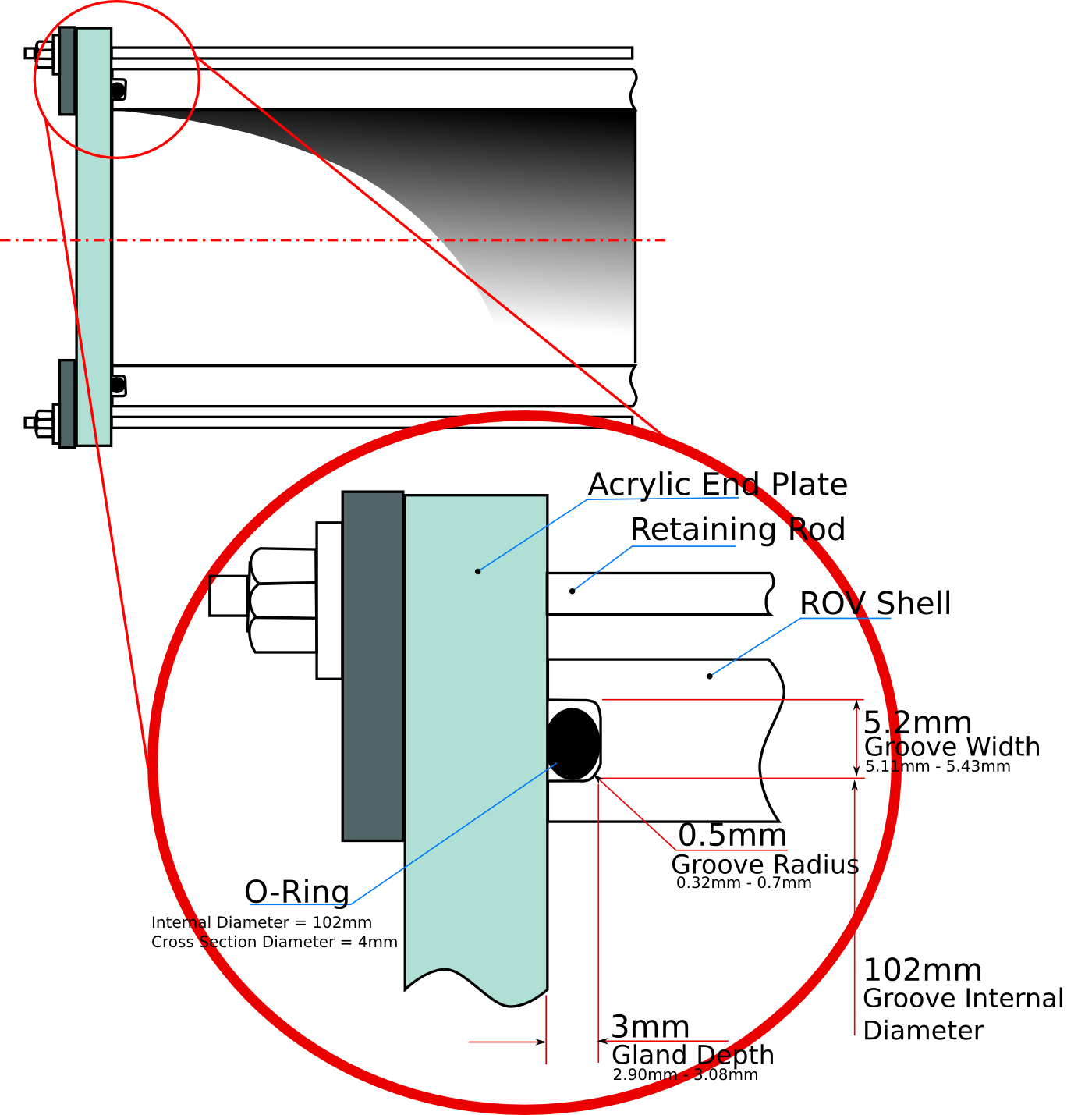
The gland dimensions above have been designed based on the guide from ESP Sealing. The same information is available from the Parker Hannifin O-ring handbook.
A subsection of the applicable table for Static Face or Flange Seals is reproduced here with interpolated data for the 102mm internal diameter 4mm cross section diameter O-ring seal required for the ROV.
Cross section diameter |
Gland Depth(in) | Static Squeeze (in) | Static Squeeze (%) | Groove Width for Liquids (in) | Groove Radius (in) | ||||||
| in | mm | Min | Max | Min | Max | Min | Max | Min | Max | Min | Max |
| 0.139 | 3.53 | 0.101 | 0.107 | 0.028 | 0.042 | 20 | 30 | 0.177 | 0.187 | 0.01 | 0.025 |
| 0.21 | 5.33 | 0.152 | 0.162 | 0.043 | 0.063 | 21 | 30 | 0.27 | 0.29 | 0.02 | 0.035 |
| 0.157 | 4 | 0.114 | 0.121 | 0.032 | 0.047 | 20 | 30 | 0.201 | 0.214 | 0.013 | 0.028 |
The bottom line in bold is an interpolation between the two other lines to calculate the values for a 4mm cross section diameter o-ring. The table below is the data for the 4mm cross section o-ring converted to metric.
| Cross section diameter | Gland Depth(mm) | Static Squeeze (mm) | Static Squeeze (%) | Groove Width for Liquids (mm) | Groove Radius (mm) | |||||
| mm | Min | Max | Min | Max | Min | Max | Min | Max | Min | Max |
| 4 | 2.90 | 3.08 | 0.81 | 1.21 | 20 | 30 | 5.11 | 5.43 | 0.32 | 0.70 |
For information and analysis of the ROV shell and Endcaps, see this page.