ROV Shell Analysis
The target depth for this ROV is 50m. This gives it some extra value because it means it can descend to depths slightly greater than a diver can easily manage. Wikipedia suggests the deepest dive for a sport diver is 40m while most dive wrecks in New Zealand waters are at depths of between 18 and 30m. The external pressure applied to the ROV at this 50m target depth is of the order of 5 atmospheres. The part most likely to crush at this pressure is the main shell and so it was carefully analysed to determine the critical pressure at which it would crush. A couple of methods were used to do the calculations so see whether they got more or less the same answer. The challenge was finding something for analysing very short pipes because most engineering data and analytical methods were for long pipes which don’t benefit from the support given by the pipe ends.
Shell Collapse Pressure
The first analysis was based on the formulas presented below which have been gathered from the paper “Collapse by Instability of Thin Cylindrical Shells Under External Pressure” by Dwight F. Windenburg and Charles Trilling Report Number 385, 1934 published in the American Society of Mechanical Engineers Transactions November 1934 Vol 56 No. 11. The paper can be downloaded from the MIT website here. The formula below is attributed to Von Mises.
Where
D = Diameter of the tube
L = Length of the tube
n = number of lobes
υ = Poisson's ratio
E = Young's Modulus of Elasticity
t = thickness of the tube wall
and
It is worth nothing that the framework to support the electronics and batteries within the ROV shell will also provide some additional resistance to buckling should the ROV body begin to deform enough to press against the internal frame.
This analysis indicated that a 350mm long PVC Pipe of 100mmNB and Pressure rating of PN15 would be able to withstand pressures to a depth of 125m, and so quite capable of lasting to our target 50m depth. The spreadsheet with this calculation can be found linked below;
- ROV_Shell.ods for the LibreOffice version
- ROV_Shell.xls for the Excel version
A lightweight steel pipe was able to withstand a far greater depth but the fact that it would also sink was a reason for using heavy duty plastic pressure pipe instead.
Circular Plate Bending
The end caps were also a component that was likely to be subjected to quite high stresses at the target depth. To model this it was assumed to behave like a circular plate with clamped edges because the rods compressing the end caps on would be unlikely to allow the edge to twist.
In the diagram above and the expressions below the variables are; p = pressure load (Pa or N/m²), r = plate radius (m), and t = plate thickness (m).
The following formula are common ones for calculating the Maximum Stress and Maximum Deflection. All units are in SI (N/m² and m).
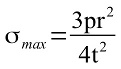
Maximum stress occurs at the edges of the plate.
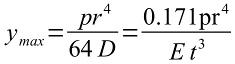
Maximum deflection y occurs at the centre of the plate. E is the Young’s Modulus of Elasticity (N/m² or Pa).
D is the flexural rigidity given by the following expression.
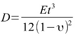
And υ is the Poisson Ratio.
The analysis indicated that 12mm thick acrylic would be suitable for the end plates. It is interesting to note that subsequent analysis using the “Under Pressure” software (described below) from DeepSea Light and Power indicated that metal end caps would deflect too much for this application. The spreadsheet with this calculation can be found linked below;
- ROV_Shell.ods for the LibreOffice version
- ROV_Shell.xls for the Excel version
Analysis using “Under Pressure” Software.
“Under Pressure” is a calculator by DeepSea Light and Power to calculate the stress and stain in cylindrical shells and circular plates subjected to external pressure. The software is designed for Windows (unfortunately does not run 100% reliably under Wine on Linux systems). It includes strength data for a number of materials including PVC pressure pipes.
The results of the analysis were;
End Plates – 12mm Acrylic.
The spreadsheet with the captured results can be found linked below;
- Under_Pressure_Analysis.ods for the LibreOffice version
- Under_Pressure_Analysis.xls for the Excel version
Note that this is a different analysis method than used above with the Von Mises equations and so will not have an exact match. The methods used in “Under Pressure” have been validated against finite element analysis calculations and so we can be reasonably confident of the suitability of the shell and end plates at the depths we are considering.
For information on Seal Design see this page.

Please Note that the formula and analysis presented here has been based on the best information available and hopefully translated through to spreadsheet calculations as accurately as possible. All endeavors have been made to ensure it all works properly and the results make sense. Despite that, there may still be errors – you will understand if you see my personality profile on the About me page.