Investigations into Wire Sealing Methods

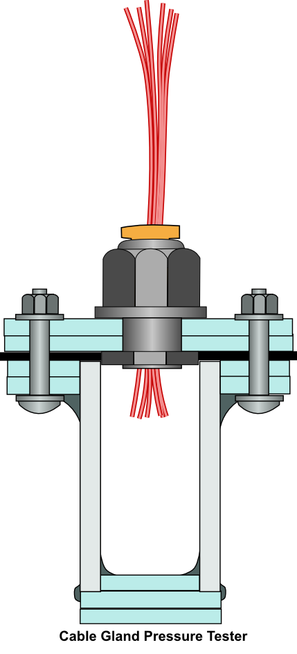
I am pleased to say that I have finally managed to come up with a method of getting the bundles of wires through a large cable gland without the water getting through as well. This method has been tested with a 5 bar pressure difference across it to simulate a depth of 50m. The test method is described on the “Pressure Testing Rig for ROV Seals” page. The various test pieces used in this development were all subjected to 5bar pressure and held at that pressure for a minimum of 30 minutes.
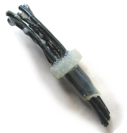
Test piece using Epoxy Glue to form a plug…..it is kinda ugly isn’t it? At least it works.
NOTE: Since this was written a more refined method has been developed which is described on this page: A More Refined Wire Sealing Technique
What Was Required
The cable glands used in the ROV design are rated for 50m depth. They were pressure tested initially using a solid plug of plastic to make sure they were up to the job – which they were.
With the exception of the tether penetration, each of the other penetrations needs to be able to seal around a bundle of at least 6 wires – three wires per motor and two motors per side. The concept I was working with was potting the wires into a tube which would then be inserted through the cable gland to achieve a good seal. I was keen to have an arrangement that allowed the cables and seal to be removed for maintenance (or incorporating more wires) without the ROV structure having to be wrecked in order to do it.
It seemed a simple and easy concept, but was somewhat harder to achieve in reality.
For completeness I have described some of the failed attempts to save others from going down those paths. You can find these at the end of this article.
The Solution that Worked
The solution that worked was a plug made from a slow setting two part epoxy glue and formed around the bundle of wires. The glue used was Norski Norstik Epoxy Glue, which looks, smells, and makes a mess in exactly the same way that Araldite does. So any equivalent two part epoxy glue that works like a long setting Araldite will work for this.
The test piece was a little rough but the length achieved was sufficient to form a good seal with the cable gland.
The advantage of this material over the silicone based solutions is that it sets hard, and also binds to the wire insulation very firmly. The slow setting time (12hrs) allowed the glue time to gradually settle into the mold and completely fill the voids between the wires.
The photo below is of the test piece used in the pressure test. As you can see it is not pretty, but it worked. Having gone through the exercise once, I can see opportunities for improving the finish. I will describe these as I describe the process I went through to make this one.
Method for Making the Wire Seal.
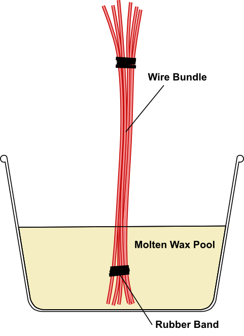
In this test piece a bundle of six wire stubs were held together with some rubber bands. The same method would be used for creating the wire seals on the actual ROV motor leads.
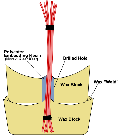
To help form a good cylindrical plug shape, paraffin wax was used as a mold. It was also used as a “barrier wall” on the bottom end of the mold to seal around the free end of the wires and prevent the epoxy glue from dropping out of the bottom of the mold. Any wax will do.
Step 1.
Pour some molten wax into a relatively deep container, and drop the end of the wire bundle into it. To keep the wire bundle vertical use something like a PCB holder, or just a piece of cardboard with a hole in it across the container’s mouth.
Leave this to set.
Potentially improved method for Step 1.
The downside of the method described above is that the wax shrinks as it cools and does not form a nice flat top surface. It also wicks in between the wires something wicked which could compromise the ability of the epoxy to penetration into the wire bundle later in the process.
An alternative is to pour your wax into a container and allow it to set without the wires in place. Once it is set remove it from the container and drill a 10mm hole into it. Use something like a hacksaw to cut across the block to make a more or less flat top surface. Return the wax block to the container. Pour some molten wax into the hole and as it sets, push the wires into the still soft wax. This should prevent the wax from wicking into the wire bundle.
Step 2.
Once the wax has set it will resemble something like the shape shown below. One of the important things to notice is that the wax will have wicked into the wire bundle. If this wax remains amongst the wires it will prevent the epoxy glue from getting into the wire bundle.
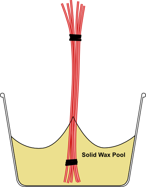
Removing the wax from between the wires is relatively easy. It can mostly be removed by picking it out with a small screw driver so tooth pick, and the remainder can be brushed out with an old toothbrush. Flexing the wires also helps to shed the wax. Once done you will have something that looks like the diagram below.
Remove the wax block from the container.
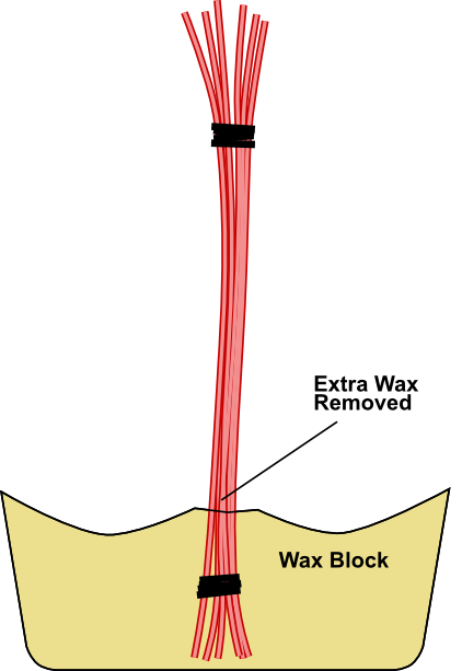
Step 3.
A later step will see another wax block, which will act as the mold for the epoxy glue wire seal, set down around the wires. In order to prevent the epoxy escaping and forming a large puddle in the space between the upper and lower wax blocks, a ring of soft clay (or plastercine) is laid around the wire bundle.
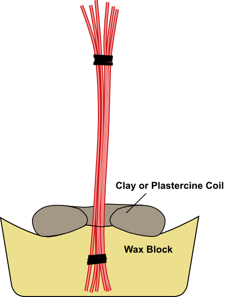
Step 4.
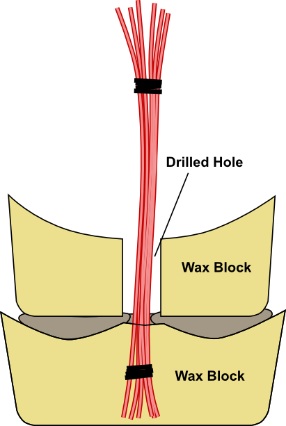
A second block of wax is slid down over the wire bundle. This one has been drilled with a 10mm diameter drill to match the size of the cable gland. This wax block will act as a mold for the epoxy glue so that it forms a cylinder around the wires with a relatively smooth surface. Care should be taken not to damage the wax hole’s walls when it is slid into place.
Pushing it down onto the lower wax block causes the wet clay or plastercine to spread and provide a good seal between the two wax blocks.
Potentially improved method for Step 4. If the lower wax block is relatively flat on its top surface, the clay ring can be quite thin or not used at all. The alternative is to weld the upper wax block to the lower one, by either dropping molten wax onto the join between the two, or use a hot metal tool to melt the join enough for it to join the two blocks.
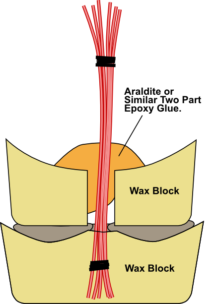
Step 5.
The epoxy glue can now be mixed as per the manufacturer’s instructions. Chances are your top block of wax has a bit of a bowl shape to it from when it solidified. This makes a handy cup for the epoxy when you pour it into the hole. I failed to get much of it in the hole when I tried to do this, but scrapping it over the hole and prodding it with a toothpick helped to encourage it down. With a long setting epoxy, it will have time to slowly flow down into the hole and allow the air bubbles to get through.
Initially it will look something like the diagram below.
Step 6.
Ideally, 12 hours later your wire seal will be solid and ready for de-molding. For my experiment it took about 3 days, because the air was pretty cold, and I wanted to make absolutely sure it was set.
The epoxy glue wire seal looks something like this once the epoxy has had time to settle.
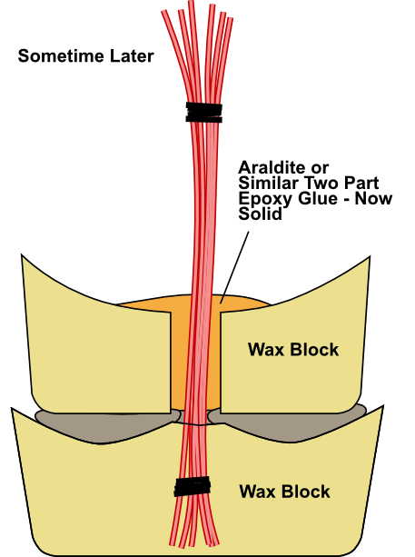
The epoxy glue forms a relatively hard finish which is ideal for this purpose. Once cured it can be removed from the wax forms.
Step 7.
I found that an old hacksaw blade heated over an old meths burner was ideal for de-waxing the wire seal. The wax can be cut away moderately close to the epoxy and then the remainder broken and scraped off with fingers. On my test one there was quite a bit of epoxy around the top which I was able to cut off with a Dremel-like rotary tool. A small hacksaw and sandpaper are also likely to be effective in tidying it up.
At the end of the process I ended up with something that looked like this image below, but as you will have seen from the photo at the top of this page, not quite as tidy.
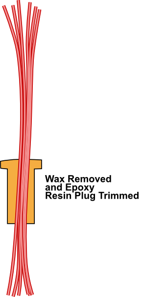
If this were the actual one for the ROV, the lower tail is where the connectors to the ESC output leads would go, and the upper wires would go to the motors. The seal would be inserted into the cable gland which is already mounted on the ROV back plate. The connectors to the ESC output leads can be soldered on at this stage.
Testing
In order to test the arrangement, I inserted it through the cable gland and tightened it up. I had dropped some epoxy on the ends of the wires earlier to prevent the water from tracking down the inside of the wires as well. The whole lot was put into the pressure testing chamber upside down. The pressure testing chamber was half full of water. The reason for putting the test piece in upside down was to make sure the wire ends and cable gland were immersed.
Once the pressure test chamber was sealed, it was pressurised to 5.5bar and held at that pressure for 30 minutes. I was very pleased to see the small test piece was completely dry inside at the end of the test. I feel it has taken me far too long to get to this point in teh development process.

Other Attempts
Prior to the Epoxy Glue solution described above, there have been about six attempts to get something that would work. What follows is a brief description of the concept and materials trialled. In most cases the test piece never made it to the pressure test rig. There were many problems with the various materials simply not curing properly, or shrinking too much.
Potting Compound in a Tube
In our work with the OpenROV, we designed the electronics pod end caps to incorporate a sort of “U” tube into which we could pour a proper potting compound. We did this because the standard design solution that the OpenROV used was impossible to get a good seal with (one of the many design cock-ups). The “U” tube arrangement worked, but unfortunately the other major cock-up with their 0-ring seal placement still meant that it leaked like a New Zealand made house. We used a potting compound called Sylgard 184 Silicone Elastomer, which was left over from some project my Partner was involved in at her work – we couldn’t afford the stuff otherwise. It is highly liquid and escapes from things far too easily, but it really is effective at getting into the gaps between wires.
The concept was to pour some of this stuff down the plastic tube holding the wires. If I poured enough in, then somewhere along its length a good seal would form.
The diagram below shows the concept for the pressure test piece and this is pretty much what it ended up looking like.
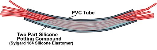
Unfortunately it never set. As far as I can tell it is still not set. Chances are the components were too old and had lost their effectiveness. I had it sitting on a warming plate for 3 days in an attempt to get it to set. Incidentally the warming plate was the 3D printer heated bed that featured in the following article on my Partner’s website. http://elfnor.com/a-novel-use-for-a-3d-heated-printer-bed.html
Polyester Embedding Resin in a Metal Tube
The concept for this was to use wax as the mold end wall, a metal tube machined to the right outside diameter to fit the cable gland, and use an embedding resin around the wires to create the seal.
I recall seeing a project when I was in school where the students were making some pendants, using embedding resin poured into metal tube cut at an angle. It was thinking about this and how hard and well bonded the material appeared to be within the metal tube that prompted this experiment. I was surprised and disappointed that the polyester embedding resin I used entirely failed to perform as I would have expected for an embedding resin. The manufacturer suggested that what I was trying to do with it was not the way it was intended to be used – apparently Kleer-Kast resin cannot be cast. How could I have been so dumb as to not realise that? I suspect an epoxy embedding resin may work in the manner I have described – after all it is not that dissimilar to the Epoxy Glue solution that worked.
In this case the resin failed to set properly, and shrunk quite badly as it cured. By the time it had fully cured, it had pulled away from the wires and left large channels clear. I will say that it flowed nicely around the wires and filled the voids well while in the liquid state.
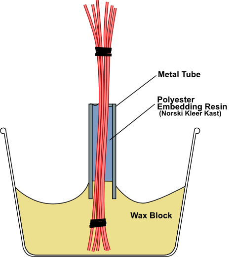
A similar test using a metal tube brushed with polishing wax to act as a mold release also failed. The idea behind this one was to form a solid resin cylinder around the wires and then remove the metal mold. Again the resin failed to cure properly, and shrunk badly. The shrinkage is fine for release from the metal tube mold but not when it lets go of the wires it was supposed to be sealing.
Polyester Embedding Resin in a Wax Mold
Because wax is a release agent for the Polyester Embedding Resin I was using, an obvious thing to make a mold from was wax. This test was carried out concurrently with the two Polyester Embedding Resin experiments using the metal tube. This was done to see how wax would work as a mold, and also be a back up should the metal tube trials fail because of difficulties with bonding to the metal tube.
Like the other attempts with the polyester embedding resin, the test failed because the resin did not cure properly and also shrunk badly. It was useful for demonstrating that the wax mold method had some potential.
Roof and Gutter Silicone
The Roof and Gutter Silicone I have used to glue the PVC pipe frame has impressed me with its strength and firmness, so I was keen to try this as a material for the wire seals. This was done concurrently with the Epoxy Glue trial and used the same arrangement of wax molds to achieve the shape. The challenge was that it was very hard to set the silicone into the hole and around the wires because it does not flow like the other materials. Using a combination of pushing it and prodding it downs the hole and wriggling the wires I managed to get it amongst the wires and some way down the hole in the wax mold. At no time was it obvious that I had managed to get the material into the hole and around the wires successfully. I think had I used the long nozzle and glue gun, I may have managed to get the silicone deeper into the mold and been more convinced of having applied it successfully.
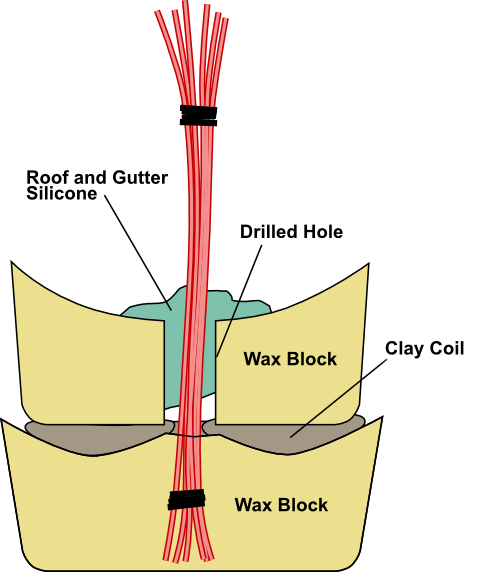
The silicone set over the next couple of days and was able to be successfully de-waxed. It had formed a patchy and flexible cylinder of silicone that was well bonded to the wires. Despite the patchy look it it, I put it into the pressure tester and held it at 5 bar for 30 minutes. A very small drop of water managed to get through. Although this was a failure, I feel that with better application, the silicone will work. The flexibility of the seal makes me a little nervous though because the seal may be compromised if the wires independently move around enough to rip the silicone.
The silicone used in this trial differs from a caulking silicone in that it is designed to have a good bond to PVC. This means that the bond with the PVC insulation on the wires is excellent and much stronger than is achieved with a Caulking Silicone.
Caulking Silicone
Caulking silicone was used in a trial identical to the one described above for the Roof and Gutter Silicone. It was very difficult to get the silicone into the mold. It cured to form a relatively soft rubbery plug, but it was not strong enough or reliable enough for this purpose.
Hot glue
In an early attempt at creating a suitable plug, hot glue was used. This was heated in a hot glue gun and injected into a plastic tube mold. Unfortunately the penetration into the bundle of wires was poor and the bond to the wire was not reliable enough.
An Alternative Scheme
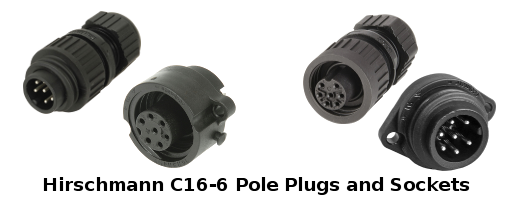
It is worth mentioning an alternative scheme that may work. This makes use of a similar industrial solution to the cable glands. Pictured are a selection of 6 pole plugs and sockets that could be mounted on the ROV endcap. The Hirschmann components pictured are all rated for 10A current, and so will be suitable for the expected motor currents. The down side is that they are only rated as IP67 which means a maximum of 1m immersion. I suspect they could be backed up with the epoxy glue described on this page to improve their seal. The line connectors include a cable gland in the back of them and so you don’t get away from needing the wire seal solution that I have described above.
 This page outlining a method for sealing wires by Hamish Trolove is licensed under a
Creative Commons Attribution-NonCommercial-ShareAlike 4.0 International License.
This page outlining a method for sealing wires by Hamish Trolove is licensed under a
Creative Commons Attribution-NonCommercial-ShareAlike 4.0 International License.