Pressure Testing Rig for ROV Seals
Things have been a little slow on the ROV project of late because I have been wrestling with building some gear to help test different methods for the cable penetrations. I am pleased to say that at least the test arrangement is now pretty much functioning sufficiently well to begin some tests.
The challenge is that I want to test the effectiveness of running bunches of wires through a silicone rubber filled tube that passes through a cable gland rated to over 50m. I am comfortable with the effectiveness of the cable glands – after all they are a tried and true industrial solution – but what I am less certain of is whether I will be able to get a good seal amongst the wires with the silicone.
In order to test this properly I need something that can give me the pressure differential across the cable gland that 50m of water will. Unfortunately the nearest water 50m deep is the Cook Strait which is a notoriously rough stretch of water. The alternative was a small chamber that I could fill with water and pressurise to 5bar with a smaller chamber within it fitted with the cable gland and wire arrangement being tested. With ambient air pressure within the small chamber, and water at 5 bar surrounding it I can simulate the conditions at 50m depth. As I found out recently when I visited Seamore Marine in Canada, this is exactly how they test all of the components they install on their ROVs.
It has taken my a couple of goes to get this right. Because it was a lot easier to work with plastics, my first attempt was constructed from PVC tubing and layered acrylic sheet for the end caps. The assembly was held together by silicone roofing glue and some threaded rod compression bars. To allow me to pressurise the chamber, I encapsulated the base of a car tyre valve within the layers of the acrylic sheet end caps. This is shown in the diagram below.
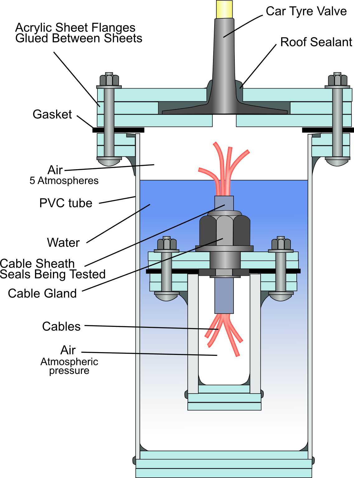
Although the lightweight PVC downpipe I was using was capable of holding the pressure, I was disappointed to find that the plastic was flexible enough to cause the silicone glue to pull away, and allow leaks to form. The best I managed to achieve was about 2 bar and even then the leakage rate was increasing faster and faster the longer I attempted to hold it at that pressure.
I was pleased to see that the layered acrylic endcaps and encapsulated car valve arrangement worked very well so I carried this design approach over to the next edition which was fashioned from some steel pipe, welded plate flanges, and a thick aluminium plate endcap. Into the aluminium plate endcap, I machined a 5mm deep cup into which a car valve could be fitted and gooped into place with roofing silicone. Below is the daigram of the steel and aluminium version that I am using at present.
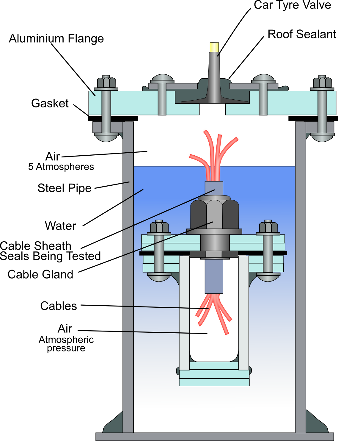
I found that I was badly out of practice with my welding and the welds I produced not only looked like a very large bird had had a big dump on it, but they were about as effective at sealing air leaks. After adding several more blobby piles of molten metal to it, I felt I had made enough of a mess and would rely on painting the thing to seal the holes. Luckily this worked. I used a Lacquer based Metal Etching Primer (the same used to paint the acrylic panels for the electronics pod) which was quite fluid and generally flowed into the gaps quite nicely. It still leaked a bit but not as much. To fix the final leaks, I applied more paint and while it was still liquid, pressurised the chamber to force the paint into the remaining holes. That seems to have worked…..finally.
Originally I had used M4 machine screws to hold the end cap on but I found I was unable to get sufficient compression on the gasket (fashioned from a truck tyre inner tube) to completely seal it without stripping the threads. M5 machine screws were able to be easily fitted and allow me to get sufficient compression on the seal to hold in excess of 5 bar.
So, as it stands the pressure tester can be pressurised up to 6 bar relatively easily, and I can maintain the pressure with the occasional puff from the compressor. The typical tests I have run thus far have been to hold a pressure in excess of 5 bar for over 30 minutes.
Here are a selection of photos of the rig in its present form.
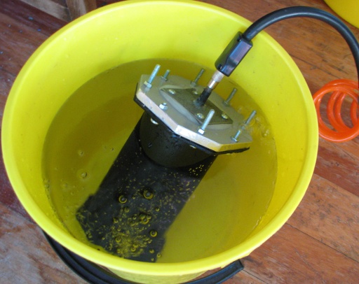
The pressure testing chamber being leak tested in a bucket of water prior to the final lot of paint being pressurised into place. As you can see there are still bubbles coming off parts of it. After I had first welded it up it looked like I had turned on the bubble jets of a spa-pool when I did this test, the leaks were so bad.
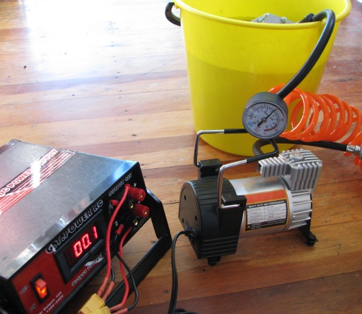
A bigger view of the test rig. The pressure gauge reads 5bar and the compressor is off.
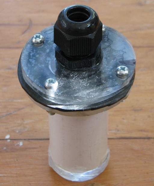
This is the cable gland holder. When a blank is fitted into the cable gland it can withstand up to 6 bar without leaking.
So hopefully once these tests are completed I will have identified a reliable way of getting the wires and tether into the ROV electronics pod. Roll on that day! Update - see below.

Success!
And that day has rolled on. Here is a successful method for creating a seal for the wire bundle.
and a more refined method is described here: A More Refined Wire Sealing Technique.