ROV Tether Management System
In stark contrast to the rest of the ROV development, the Tether Management System (TMS) went together very quickly and easily. Including time lost due to me not fully checking which bits were moving relative to other bits and installing the swivel connector the wrong way around, I had the TMS completed within a day and a half.
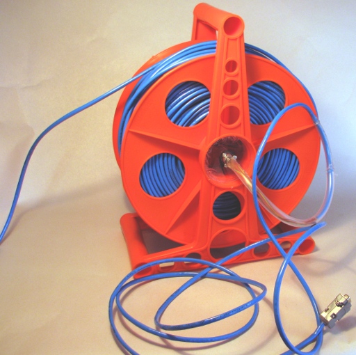
I wanted to create a good robust and easy to use TMS that worked somewhat better than the very unsatisfactory arrangement we have on the OpenROV. The easy solution was to make use of a hose reel and swivel connector. This would keep the CAT5 cable knot free and easy to extend and reel back in.
To this end I went down to the local Mitre10 hardware store and as I walked toward the gardening section, I was faced with a display of large 100% plastic power cable caddies for an extraordinarily good price ($15 If I recall). It also had a large empty hub that would be ideal for installing the swivel connector.
I had wanted something that was mainly plastic, or aluminium in order to withstand use near the sea – these 100% plastic ones were ideal. Seeing as I was near the gardening section I had a quick look at what was available and there was a hose reel for about the same price but on closer inspection what appeared to be a plastic frame was a white painted plastic and therefore not suitable. So I left the store very pleased to have found exactly what I was after.
The swivel connector was also relatively easy to find through DX. They stock a large range of slip-ring swivel connectors that have anywhere from two conductors up to about 18, and some of them can carry very large currents and high voltages (up to 15A and 240V). They also have a maximum speed of 250rpm. I would have to be winding the ROV in pretty fast for me to even get close to that.
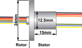
In the end I opted for a 6-conductor slip ring device rated at 1.5A. At this stage I did not know what sort of reel arrangement I would have, so I was careful not to get too excited about the larger high current swivel connectors. The 6-conductor slip ring swivel connector was quite a nice size with a 24mm outer flange and a 12.5mm diameter slip-ring stator housing.
Here are the basic specifications of the 6-conductor slip ring set:
|
Circuits: |
6 |
|
Current: |
1.5A /Circuit |
|
Diameter: |
12.5mm |
|
Operating Speed: |
250rpm |
|
Temperature Range: |
-20~ +60'C |
|
Contact Material: |
Gold / gold |
|
Lead Size: |
AWG30 Silver plated copper UL,Teflon |
|
Lead Lengths: |
Standard 300 mm |
|
Dielectric strength: |
500VAC @50Hz,between each circuit |
|
Insulation resistance: |
1000Mohm @ 500VDC |
If it is any help, the DX catalogue number is “SKU: 388281”
To put the TMS together, I drilled a hole in the core of the plastic cable caddy, and after cutting off a length of CAT5 cable to run from the TMS to the control box, I threaded the cable through a hole enough for me to get at the ends of it. Taking very careful note of which colour wires I was connecting to which pair in the CAT5 cable, I soldered the CAT5 cable to the rotor wires of the Slip-ring connector.
That done I quickly manufactured a disk out of waste acrylic that would fit into the hub of the plastic cable caddy. A 13mm hole drilled in the centre and three smaller screw holes saw the completion of a plate through which the slip-ring swivel connector stator would pass, and which could be sealed into the hub of the plastic cable caddy.
With the plastic disk in place around the Slip-ring swivel connector stator, I was able to solder the wires from the stator to the short length of CAT5 cable that would go to the topside control box. Silicone PVC glue was used to glue the acrylic disk into the hub of the plastic cable caddy. That was the TMS essentially finished.
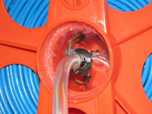
The TMS core showing the swivel arrangement.
As I wound the 100m of CAT5 cable onto the caddy I was pleased to see that the caddy really was big enough, and that the swivel arrangement worked well. Because the wires on the Slip-ring swivel connector are fairly light I was a little concerned about the wear and tear on them. To protect them, I put some silicone sealant over them and sealed a length of plastic hose up against it to reduce the amount of pull that would be applied to the wires. It is a little ugly but I am confident that it will protect them from breaking and pulling out.
Had I not already made the epoxy glue plug for the CAT5 cable for where it enters the ROV, I would have made it at this point in the process. Because it was already done, it was a small job to take the next step and install it into the ROV’s endcap. For the connection within the ROV I used a 5-wire JST(?) connector as used on 4S LiPo battery balance plugs.
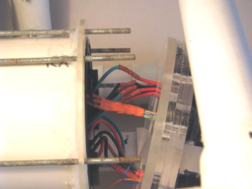
The Tether within the ROV Body.
At the topside end I used a DB9 socket to pass the serial connection RX,TX, and GND, and the Video and Video ground signals.
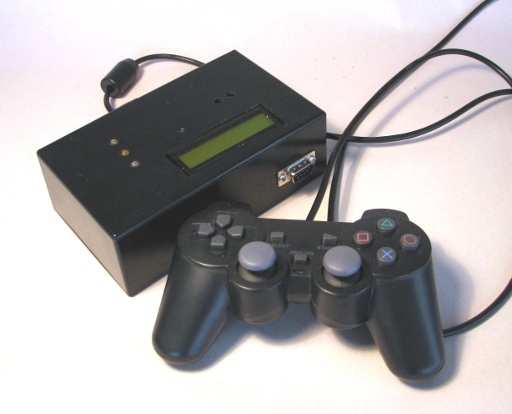
The Topside Box and Controller.
When I connected up the entire ROV system including video, I was pleased and very relieved to see that it all worked 100% with video and communications running smoothly over the 100m tether and associated Tether Management System. Lights, Camera, Action! Woo hoo!