ROV Idle Sketch
When you are building or developing something on the ROV and you have the electronics in place, there are times when you want to apply power to the system but you don’t want everything to go wild. This “Do Nothing” sketch initialises the ESCs then puts the ROV system into a neutral or Idle state with the ESCs set to 90° degrees which is their neutral position and the camera pitch servo to 90° degrees. The camera triggers are all set to HIGH which is the state for not triggered. Once that is all done it just sits there and flashes the red LED on the circuit board.
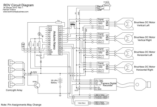
The circuit is the one described on this page, and shown below.
The sketch below can be downloaded from here: ROVDoNothing.ino
The Arduino Sketch
/*
ROVDoNothing.ino
This sketch is designed to set the ROV systems to idle so that
work can be done on it without it running motors, lights, or
complaining about not having any input.

The pin assignments are;
D13 = RED LED pin.
D11 = Jumper pin
D5 = ESC Horizontal Right
D6 = ESC Horizontal Left
D7 = ESC Vertical Right
D8 = ESC Vertical Left
D12 = Headlights control

D3 = Video Trigger
D2 = Photo Trigger

Please note that the ESCs will all have been programmed by this
point in the project.
*/

#include <Servo.h>

Servo ESCVL;  // Create Servo Object ESC Vertical Left
Servo ESCVR;  // Create Servo Object ESC Vertical Right
Servo ESCHL;  // Create Servo Object ESC Horizontal Left
Servo ESCHR;  // Create Servo Object ESC Horizontal Right

const int RedLEDpin = 13; // The indicator LED pin is 13.
const int HeadLts = 12; // The Headlight Control is on pin 12
const int CamRecTrig = 3; //Camera video recorder trigger is on pin D3
const int CamPhotTrig = 2; //Camera photo trigger is on pin D2

int throttle = 0;  //variable for the throttle setting that will
                   // be send to each ESC.

void setup()
{
  pinMode(RedLEDpin,OUTPUT);
  pinMode(HeadLts,OUTPUT);
  pinMode(CamRecTrig,OUTPUT);
  pinMode(CamPhotTrig,OUTPUT);
  ESCVL.attach(8,600,2250); //attach the ESCVL to pin 8
  ESCVR.attach(7,600,2250); //attach the ESCVR to pin 7
  ESCHL.attach(6,600,2250); //attach the ESCHL to pin 6
  ESCHR.attach(5,600,2250); //attach the ESCHR to pin 5
    //Due to problems with the ESC recognising the maximum
    //position at the default settings, the figures after
    //the pin number are the microsecond signals for the
    //minimum and maximum that the ESC will recognise.
    // 600 and 2250 work.

  throttle = 90;  //Set throttle to the neutral position.
  ESCVL.write(throttle);  //Set the ESCVL signal to the neutral position.
  ESCVR.write(throttle);  //Set the ESCVL signal to the neutral position.
  ESCHL.write(throttle);  //Set the ESCVL signal to the neutral position.
  ESCHR.write(throttle);  //Set the ESCVL signal to the neutral position.
  digitalWrite(HeadLts, LOW); //Set the Headlights to Off
  digitalWrite(CamRecTrig,HIGH); //Both camera functions are triggered
  digitalWrite(CamPhotTrig,HIGH); // by making the pin low.

  delay(10000);   //Ten second delay
    //The ESC should now be initialised and ready to run.

}


void loop()
{
  digitalWrite(RedLEDpin, HIGH);
  delay(1000);
  digitalWrite(RedLEDpin, LOW);
  delay(1000);
}