Communication between Arduinos – Serial
This pair of sketches does the same as the I2C communication experiment where one Arduino is the Master issuing orders to the Slave Arduino which takes the orders and turns them into action. This experiment takes the variable resistance output from an old PC Raider joystick (one axis only) and actuates a servo to match it on another Arduino. All communications between the two Arduinos is through Serial Communication. Serial communication allows us to use longer connection wires. The length of the wire can be increased disproportionately with as the baud rate is reduced. For a baud rate of 9600 the maximum connection length is around 300m which is more than adequate for the needs of this project. The purpose of this sketch was to test the options for long distance wired communication for the ROV project.
Because we are using Serial to communicate between the Arduinos, an extra Serial port needs to be created on the UNO Master so that we can still monitor things on the computer through its USB serial port. For this experiment we have used a MEGA and connected the Arduino to Arduino communication it is Serial1 Port. This leaves the regular serial port free for us to monitor it using the computer.
A push button to enable/and disable the two arduinos has been introduced to ensure the Serial Ports are free for uploading from the computer. LEDs indicate the status.
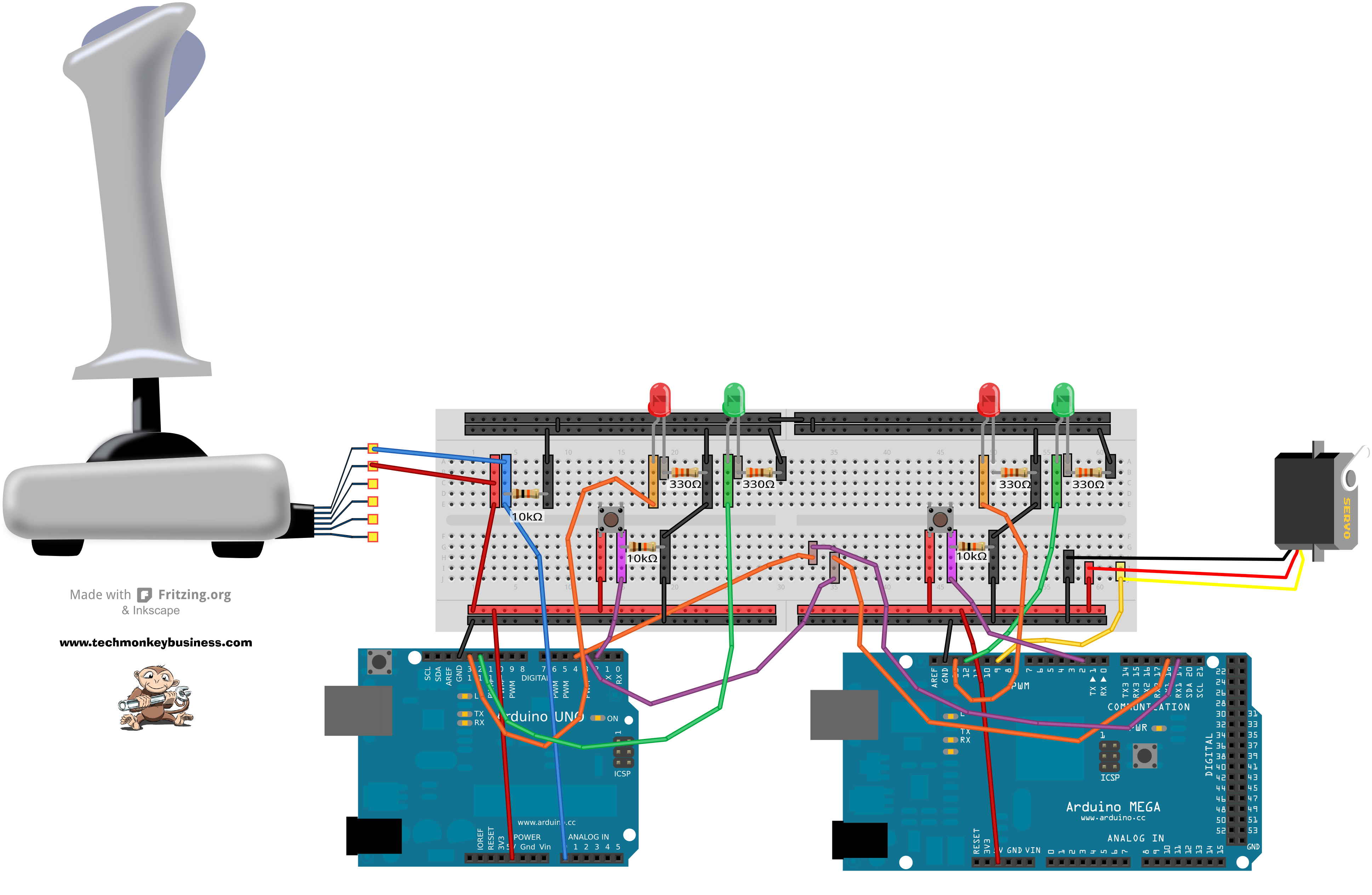
'’Note’’ that there is a cross over between the serial communication lines Rx to Tx on one line and Tx to Rx on the other.
Both the Master and Slave sketches can be downloaded from here: Serial_Joystick_Masterv1_and_Slavev2.zip
Sketch for the Arduino UNO Master
/* Serial_Joystick_Masterv1 - Working
This sketch is one of two for sending information between two
Arduinos using serial communication to achieve communication down
a long wire.
This sketch is the master and will read a single channel from
a PC Raider Joystick (Potentiometers)on analogue pin 0, and send
the data to a slave Arduino via the Serial Port (Digital pins 0 and 1)
The slave Arduino will take that information and use it to move a servo.

This sketch also includes an interrupt button to enable and disable
sketch.  This is included so that the sketch can be stopped to allow
new uploads seeing as it is using Serial and I2C communication that
would otherwise block this process.  LEDs are used to indicate the
enabled or disabled state.

This sketch is based on I2C-Masterv0_Joystickv0
*/

#include <SoftwareSerial.h>

const int rxpin = 3;  // New Serial receive pin on UNO
const int txpin = 4;  // New Serial Transmit pin on UNO
SoftwareSerial serial_ard(rxpin, txpin);  //Set up the extra Serial Port
int potpin = 0; // analog pin used to connect the Joystick
int val;  // variable to read the value from the analog pin
const int grnLEDpin = 12;  //green LED is on Digital pin 12
const int redLEDpin = 13;  //red LED is on Digital pin 13.
const int Button = 2;  //Button is on Digital pin 2
volatile boolean Toggle;    //Introduce the controlling switch.
  //which will change with the interrupt.

void setup()
{
  Serial.begin(9600);  //Port for communication to computer for debugging
  serial_ard.begin(9600);  //Baud 9600 is good for 300m lines.
  pinMode(grnLEDpin, OUTPUT);  //Sets the grnLEDpin to output
  pinMode(redLEDpin, OUTPUT);  //Sets the grnLEDpin to output
  pinMode(Button,INPUT);  //Sets the Button to input.
  Toggle = false;  //Sets the condition toggle
  attachInterrupt(0,FFlag,FALLING);  //Sets up the Interruptor
    //on pin 2,and calls subroutine FFlag when the button value falls.
   //using FALLING helps avoid the blink jittering if the button is held.
}

void loop()
{
  if(Toggle == false)
  {
    digitalWrite(redLEDpin,HIGH); // indicate system disabled by using red LED
    digitalWrite(grnLEDpin,LOW);  // indicate system disabled by turning off green LED
  }
  else
  {
    digitalWrite(redLEDpin,LOW); // indicate system enabled by turning off red LED
    digitalWrite(grnLEDpin,HIGH);  // indicate system enabled by lighting green LED
    DoStuff();  //Execute the DoStuff subroutine.
  }
  delay(15);  // 15 millisecond delay
}

void DoStuff()
{
  val = analogRead(potpin);// reads the value of the joystick (value between 0 and 1023)
  val = map(val, 415, 1023, 0, 179);
  // scale it to use it with the servo (value between 0 and 180)
  Serial.println(val); // Send the Joystick sensor value to the Monitor
  serial_ard.println(val);  //Send the Joystick value to the Slave Arduino
}

void FFlag()
{
  Toggle = !Toggle; //The should switch the value - "!" means NOT
}
Sketch for the Arduino MEGA Slave
/* Serial_Slavev2 - Working
This sketch is one of two for sending information between two
Arduinos.  This one is the slave and will take the value
corresponding to a Joystick position which has been sent via
the Serial communication.  The this value will be used to move a servo.

This development sketch needs an Arduino Mega so that the commands
from the Master can be received into an alternative Serial Port
and still be able to report to the computer through the regular
Serial Port.

This sketch also includes an interrupt button to enable and disable
sketch.  This is included so that the sketch can be stopped to allow
new uploads seeing as it is using Serial and I2C communication that
would otherwsie block this process.  LEDs are used to indicate the
enabled or disabled state.

Based on I2C_Slavev2
*/
#include <Servo.h>
Servo myservo; // create servo object to control a servo
int val=90;  // scaled variable transmitted via Serial Comms - default is neutral 90degrees
const int grnLEDpin = 12;  //green LED is on Digital pin 12
const int redLEDpin = 13;  //red LED is on Digital pin 13.
const int Button = 2;  //Button is on Digital pin 2
volatile boolean Toggle;    //Introduce the controlling switch.
  //which will change with the interrupt.

void setup()
{
  pinMode(grnLEDpin, OUTPUT);  //Sets the grnLEDpin to output
  pinMode(redLEDpin, OUTPUT);  //Sets the grnLEDpin to output
  pinMode(Button,INPUT);  //Sets the Button to input.
  Toggle = false;  //Sets the condition toggle
  Serial.begin(9600);  //Serial port for computer communications
  Serial1.begin(9600);  //Serial port for Master communications
  myservo.attach(9);// attaches the servo servo on pin 9 to the servo object
  attachInterrupt(0,FFlag,FALLING);  //Sets up the Interruptor
    //on pin 2,and calls subroutine FFlag when the button value falls.
   //using FALLING helps avoid the blink jittering if the button is held.
}

void loop()
{
  if(Toggle == false)
  {
    digitalWrite(redLEDpin,HIGH); // indicate system disabled by using red LED
    digitalWrite(grnLEDpin,LOW);  // indicate system disabled by turning off green LED
  }
  else
  {
    digitalWrite(redLEDpin,LOW); // indicate system enabled by turning off red LED
    digitalWrite(grnLEDpin,HIGH);  // indicate system enabled by lighting green LED
    DoStuff();  //Execute the DoStuff subroutine.
    myservo.write(val); // sets the servo according to the scaled value received through the Serial
  }
  delay(15);  // 15 millisecond delay
}

void DoStuff()  //how many degrees for the servo
{
  if(Serial1.available()) //while there is data available
  {
    val=Serial1.parseInt();  //pull out the numerical bit
    Serial.print(val);  //report on what is happening
  }
}

void FFlag()
{
  Toggle = !Toggle; //The should switch the value - "!" means NOT
}