Communication between Arduinos - I2C
I2C can be used to communicate between two Arduinos but it must be over a very short wire. The capacitance in long wires prevents I2C from working. Use Serial to communicate between Arduinos for longer connections.
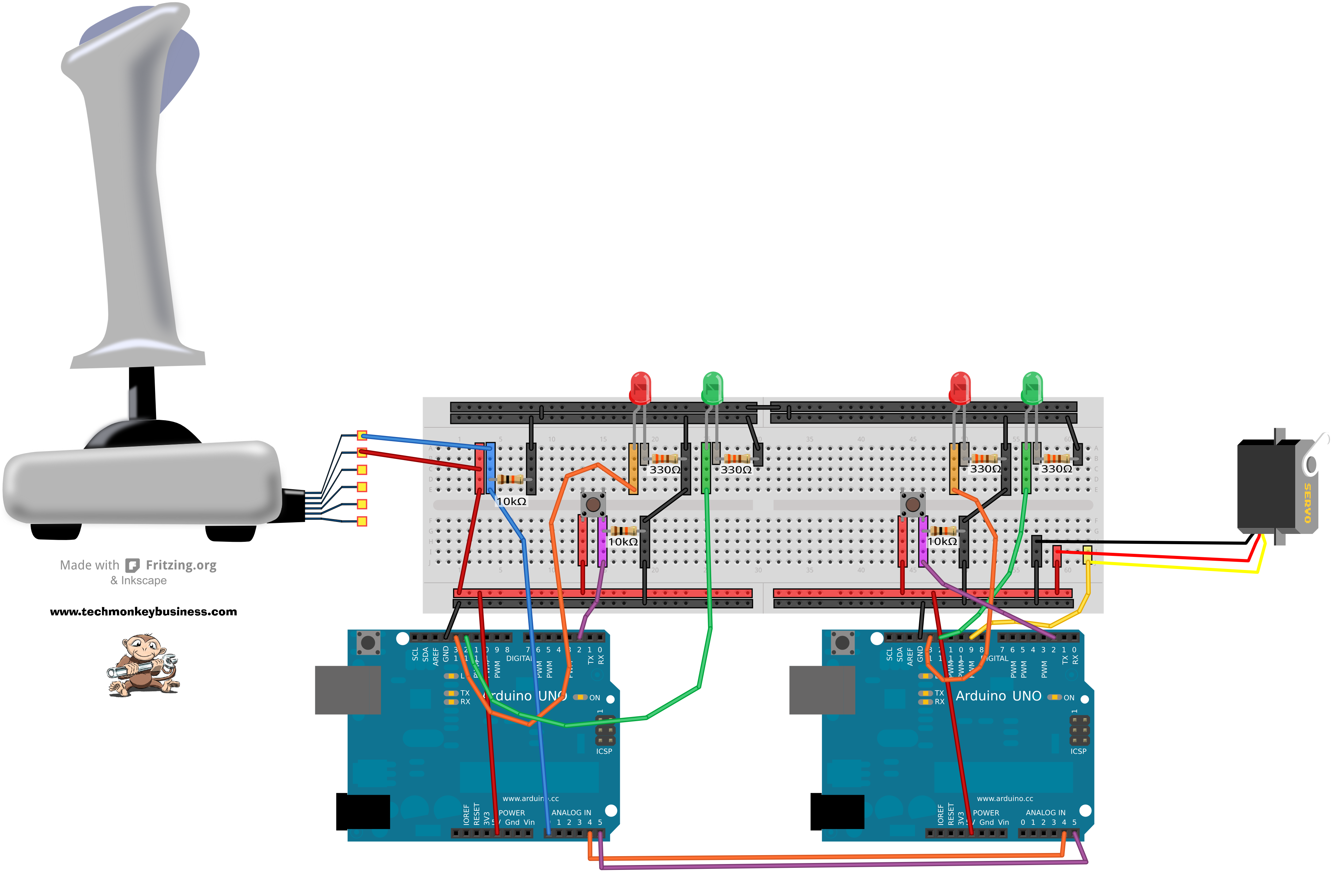
The system presented here is a development sketch for the ROV system that uses two arduinos; one acting as a Master and the other as a Slave. The Master takes the variable resistance signal from an old PC Raider joystick through its Analogue port A0 and converts it into a scaled value between 0 and 179 for transmission over the I2C connection to the slave. The Slave captures the ASCII message from the I2C bus and uses this to control the position of a servo. It could just as easily be controlling an ESC and brushless DC motor combination for a vehicle.
You can download both sketchs from here: I2C_Masterv2_Joystickv0_and_Slavev2.zip
Code for the Master
/* I2C-Masterv0_Joystickv0
This sketch is one of two for sending information between two
Arduinos.  This one is the master and will read a single channel from
a PC Raider Joystick (Potentiometers)on
analogue pin 0, and send the data to a slave Arduino via the I2C
communication.  The slave Arduino will take that information and
use it to move a servo.

This sketch also includes an interrupt button to enable and disable
sketch.  This is included so that the sketch can be stopped to allow
new uploads seeing as it is using Serial and I2C communication that
would otherwsie block this process.  LEDs are used to indicate the
enabled or disabled state.
*/

#include <Wire.h>
const int address = 4;  //The address for communications note that
  // this is one of the dedicated I2C connections.
int potpin = 0; // analog pin used to connect the Joystick
int val;  // variable to read the value from the analog pin
const int grnLEDpin = 12;  //green LED is on Digital pin 12
const int redLEDpin = 13;  //red LED is on Digital pin 13.
const int Button = 2;  //Button is on Digital pin 2
volatile boolean Toggle;    //Introduce the controlling switch.
  //which will change with the interrupt.

void setup()
{
  Serial.begin(9600);
  Wire.begin();
  pinMode(grnLEDpin, OUTPUT);  //Sets the grnLEDpin to output
  pinMode(redLEDpin, OUTPUT);  //Sets the grnLEDpin to output
  pinMode(Button,INPUT);  //Sets the Button to input.
  Toggle = false;  //Sets the condition toggle
  attachInterrupt(0,FFlag,FALLING);  //Sets up the Interruptor
    //on pin 2,and calls subroutine FFlag when the button value falls.
   //using FALLING helps avoid the blink jittering if the button is held.
}

void loop()
{
  if(Toggle == false)
  {
    digitalWrite(redLEDpin,HIGH); // indicate system disabled by using red LED
    digitalWrite(grnLEDpin,LOW);  // indicate system disabled by turning off green LED
  }
  else
  {
    digitalWrite(redLEDpin,LOW); // indicate system enabled by turning off red LED
    digitalWrite(grnLEDpin,HIGH);  // indicate system enabled by lighting green LED
    DoStuff();  //Execute the DoStuff subroutine.
  }
  delay(15);  // 15 millisecond delay
}

void DoStuff()
{
  val = analogRead(potpin);// reads the value of the joystick (value between 0 and 1023)
  val = map(val, 415, 1023, 0, 179);
  // scale it to use it with the servo (value between 0 and 180)

  Wire.beginTransmission(address);  //transmit to the slave
  Wire.println(val);  // Send the Joystick sensor value to the Slave
  Serial.println(val);
  Wire.endTransmission();
}

void FFlag()
{
  Toggle = !Toggle; //The should switch the value - "!" means NOT
}
Code for the Slave
/* I2C-Slavev2
This sketch is one of two for sending information between two
Arduinos.  This one is the slave and will take the value
corresponding to a flex sensor position which has been sent via
the I2C communication.  The this value will be used to move a servo.

This sketch also includes an interrupt button to enable and disable
sketch.  This is included so that the sketch can be stopped to allow
new uploads seeing as it is using Serial and I2C communication that
would otherwsie block this process.  LEDs are used to indicate the
enabled or disabled state.
*/

#include <Wire.h>
#include <Servo.h>
const int address = 4;  //The address for communications note that
  // this is one of the dedicated I2C connections.
Servo myservo; // create servo object to control a servo
int val=0;  // scaled variable transmitted via I2C
const int grnLEDpin = 12;  //green LED is on Digital pin 12
const int redLEDpin = 13;  //red LED is on Digital pin 13.
const int Button = 2;  //Button is on Digital pin 2
volatile boolean Toggle;    //Introduce the controlling switch.
  //which will change with the interrupt.

void setup()
{
  Wire.begin(address);
  pinMode(grnLEDpin, OUTPUT);  //Sets the grnLEDpin to output
  pinMode(redLEDpin, OUTPUT);  //Sets the grnLEDpin to output
  pinMode(Button,INPUT);  //Sets the Button to input.
  Toggle = false;  //Sets the condition toggle
  Serial.begin(9600);
  myservo.attach(9);// attaches the servo servo on pin 9 to the servo object
  attachInterrupt(0,FFlag,FALLING);  //Sets up the Interruptor
    //on pin 2,and calls subroutine FFlag when the button value falls.
   //using FALLING helps avoid the blink jittering if the button is held.
  Wire.onReceive(receiveEvent);  //If something comes through the I2C jump to receiveEvent Subroutine
  Serial.println("Hi");
}

void loop()
{
  if(Toggle == false)
  {
    digitalWrite(redLEDpin,HIGH); // indicate system disabled by using red LED
    digitalWrite(grnLEDpin,LOW);  // indicate system disabled by turning off green LED
  }
  else
  {
    digitalWrite(redLEDpin,LOW); // indicate system enabled by turning off red LED
    digitalWrite(grnLEDpin,HIGH);  // indicate system enabled by lighting green LED
  }
  delay(15);  // 15 millisecond delay
}

void receiveEvent(int Deg)  //how many degrees for the servo
{
  int value = 0;
  while(Wire.available()>0)  //while there is data available
  {
    char c = Wire.read();  //receive data from I2C and put it on global variable val
    if(isdigit(c))  //Check to see if ASCII in range 48 to 57
    {
      value=(value*10)+(c-'0');  // accumulate the value
    }
    else if(c ==10) //new line ASCII character
    {
      val = value;  // put the new value into global variable
      value = 0;
    }

  }
  myservo.write(val); // sets the servo according to the scaled value received through the I2C
}

void FFlag()
{
  Toggle = !Toggle; //The should switch the value - "!" means NOT
}