Hmc5883l_digital_compass
This is a simple sketch to test out the HMC5883L based digital compass for potential inclusion in the ROV project. At present the ROV pilot has only their own spacial sense and the video feed to determine where they are and which way they’re facing. By adding in a digital compass and having it sending data to the topside control display will hopefully reduce the chance of the pilot becoming disorientated.
The HMC5883L is typically available on a small breakout board from suppliers such as DX. Depending on which port you connect to, it can be run using 3.3V or 5V. The communication protocol is i2c. It has the ability to provide a 3D heading direction based on the earths magnetic field but in this example we will only be looking at the X and Y components.
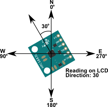
The directions are marked on the board with a set of axis. The X-axis is forward and gives the heading.
In this example the output is displayed on a 16x2 LCD screen. The diagram below shows the connections. If you wanted to run the device without being connected to a USB power supply, the dotted lines show where the external 5V supply should connect in.

The Code
You can download this sketch here: DigitalCompassv2.ino
/*
DigitalCompassv2.ino
Hamish Trolove - 13 July 2015
www.techmonkeybusiness.com
This sketch makes use of the HMC5883L based digital
compass and 16 x 2 LCD display to provide
heading readings.

The Pin assignments
LCD Display
Back light is connected to the 5V supply and Ground
therefore not controlled by the Arduino pins.
  VSS to GND
  VDD to 5V
  VO to sweep arm of 10kohm variable resistor
  RW to GND
  LCD RS - D12
  LCD E  - D11
  LCD D7 - D10
  LCD D6 - D9
  LCD D5 - D8
  LCD D4 - D7

HMC5883L Digital Compass
Connected to Ground and the 3.3V Supply pin on the Arduino
  SDA - Analogue 4
  SCL - Analogue 5
*/

#include <LiquidCrystal.h>
#include <Wire.h>  //i2c library for the Digital Compass


LiquidCrystal lcd( 12, 11, 7, 8, 9, 10 );
//Pins for the 16 x 2 LCD Display
//LiquidCrystal(rs, enable,d0,d1,d2,d3,d4,d5,d6,d7)

const int hmc5883Address = 0x1E; //0011110b, I2C 7bit address for compass
const byte hmc5883ModeRegister = 0x02;
const byte hmcContinuousMode = 0x00;
const byte hmcDataOutputXMSBAddress = 0x03;

void setup()
{
  // set up the LCD's number of columns and rows:
  lcd.begin(16, 2);
  lcd.clear();  //make sure screen is clear.
  lcd.print("Compass is Go");
  delay(1000);
  Wire.begin(); // Start the i2c communication


  //Initialise the Digital Compass
  Wire.beginTransmission(hmc5883Address);  //Begin communication with compass
  Wire.write(hmc5883ModeRegister);  //select the mode register
  Wire.write(hmcContinuousMode); //continuous measurement mode
  Wire.endTransmission();

}

void loop()
{
  int x,y,z; //triple axis data.
  //Tell the HMC5883L where to begin reading the data
  Wire.beginTransmission(hmc5883Address);
  Wire.write(hmcDataOutputXMSBAddress);  //Select register 3, X MSB register
  Wire.endTransmission();

  //Read data from each axis
  Wire.requestFrom(hmc5883Address,6);
  if(6<=Wire.available())
  {
    x = Wire.read()<<8; //X msb
    x |= Wire.read();   //X lsb
    z = Wire.read()<<8; //Z msb
    z |= Wire.read();   //Z lsb
    y = Wire.read()<<8; //Y msb
    y |= Wire.read();   //Y lsb
  }


  int angle = atan2(-y,x)/M_PI*180;
  if (angle < 0)
  {
    angle = angle + 360;
  }

  //Reporting the data to the LCD Screen
  lcd.clear();  //make sure screen is clear again.
  lcd.setCursor(0,0); //Top left hand corner
  lcd.print("XYZ:");
  lcd.setCursor(0,1); //Bottom left corner
  lcd.print("Dir(deg):");

  lcd.setCursor(4,0);
  lcd.print(x);
  lcd.setCursor(9,0);
  lcd.print(y);
  lcd.setCursor(13,0);
  lcd.print(z);

  lcd.setCursor(9,1);
  lcd.print(angle);

  delay(250);

}