ROV Control Sketches – Third Edition
The latest edition of this control system can be found here: ROV Control Sketches – Fourth Edition

This is the third release of the pair of Arduino Sketches used to control the ROV. This edition builds on the second edition, and corrects the signals sent to the ESCs to ensure the motors are turning in the correct direction and maximum output from the ESCs can be achieved in the most important directions; forward and down. It also implements the proper camera control signals for the HoryzonHD v3 Camera. For the sake of completeness, some of the details from the previous editions have been repeated here.
A PS2 controller is used for the operator’s input, and a 16x2 LCD display is use to show the battery voltage in the ROV, the temperature within the ROV, and other data. Provision has been made in the code for display of depth and heading information. A series of three LEDs provide feedback on the probable status of the ROV headlights, whether the camera is recording or not and an indication that a photo has been triggered. Another two LEDs provide warning signals in the case of low battery voltage on board the ROV or too high temperature within the ROV. The circuit is described on this page: ROV circuit description, and shown below. Click on the image below to go to a higher resolution pdf version.
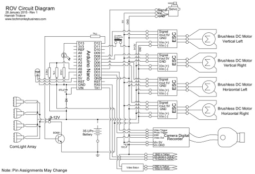
The ROV and the topside system are connected via a 100m CAT5 tether. Communication between the Topside Arduino (Master) and the ROV Arduino (Slave) makes use of the EasyTransfer library by Bill Porter.
As it happens, the video output from the Horyzon camera includes icons that report the status of the camera. It tells the operator whether it is in video mode, recording video, camera mode, or taking a photo. Because this is an accurate indication of what the camera is doing rather than the “best guess” indication provided by the topside Arduino and status LEDs, this part of the code will be removed in the next edition and the ROV circuits updated to remove the two camera status LEDs.
The HobbyWing EZRUN 18A ESCs used need to be programmes and calibrated before use in this system. The process to do this is described in this article: Programming and Calibration the EZRUN 18A ESCs
Controlling the ROV
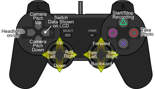
The Playstation 2 controller is a nice cheap control interface with more buttons and controls than are required for this project. like the previous editions of the ROV control sketches, the PS2 controller is used for controlling things on the ROV such as the motors, lights, and camera, as well as being able to flick through the data being displayed on the topside station’s LCD display. This uses the PSX library from Bill Porter.
For more discussion on using the PS2 controller and Arduino to manipulate stuff, have a look at this page.
At present these are the controls being used.
Topside Station Circuits
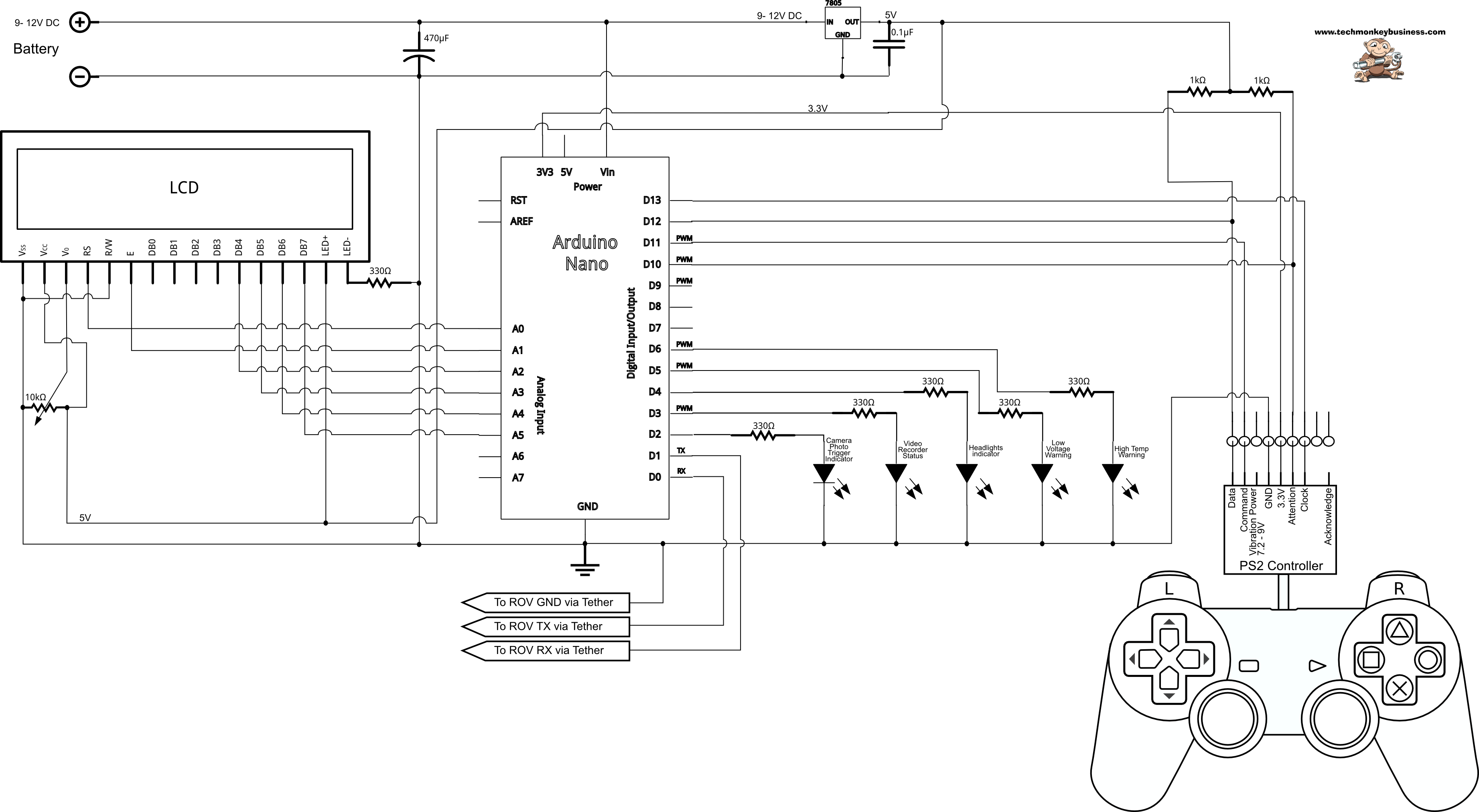
In addition to the PS2 Controller, the topside station makes use of an Arduino Nano and a 16x2 LCD Display. A 78T05CT regulator is used to provide a 5V supply to the LCD Display and for the Command and Attention pins of the PS2 controller. The LCD library is part of the standard Arduino IDE, so you will not need to hunt around for this in order to get this sketch to work. Click on the images below to see a higher resolution version.
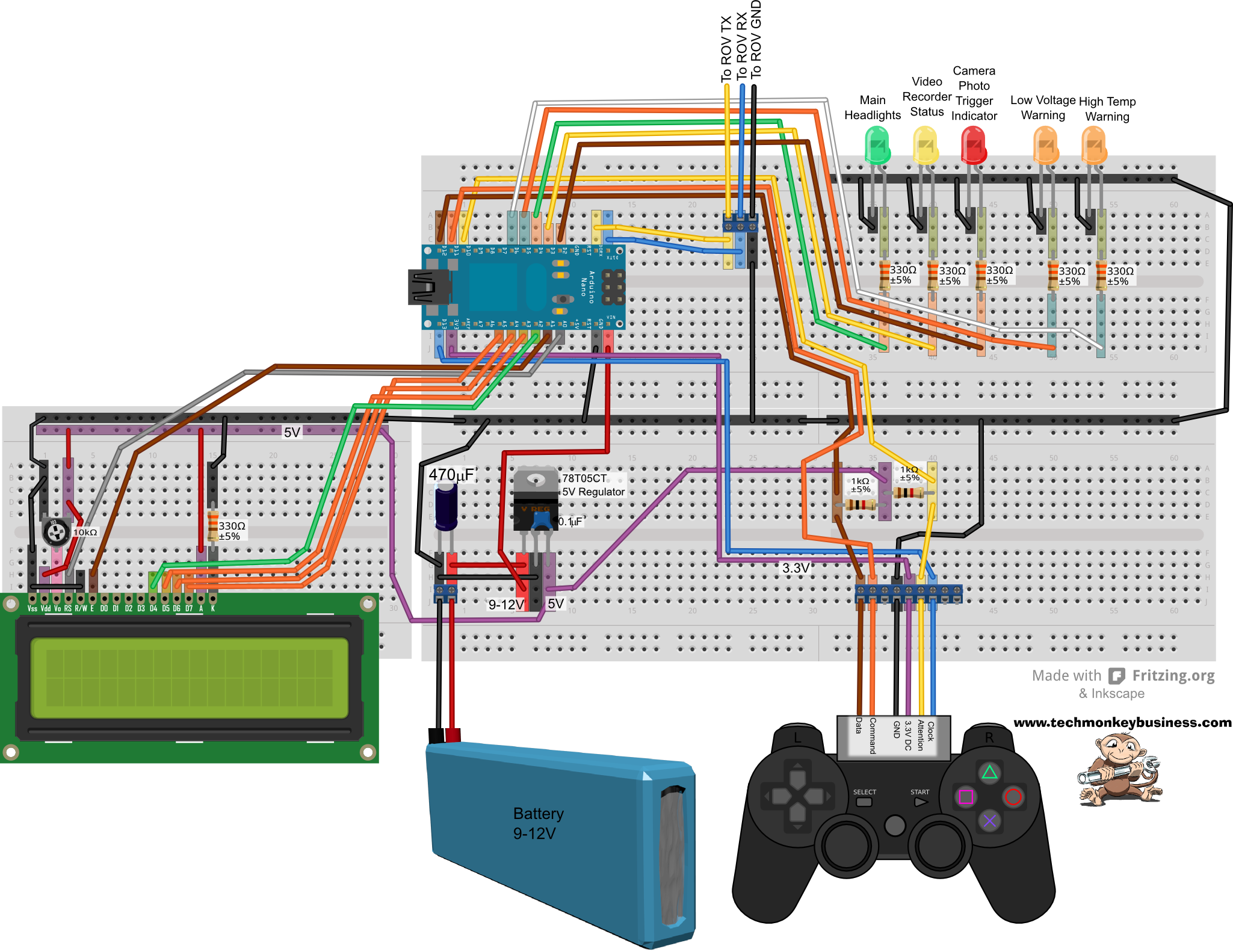
Or if you prefer a more classic circuit diagram.
The Sketches
The sketches make use of two libraries that will need to be installed into the Arduino IDE.
- Bill Porter’s PSX library which can be found here www.billporter.info.
- And Bill Porter’s EasyTransfer library which can be found on the same website.
The two sketches presented below can be downloaded from here: ROVPS2Control_Sketches_Release3.zip
You can also download the libraries from the following webpage: A Collection of Arduino Libraries Used in This Project.
Topside Arduino Sketch - aka the “Master”
The commands from the PS2 controller are translated to actual motor speeds and directions on the Master rather than the slave. The messages back from the ROV are the ROV battery voltage, the internal temperature, and when available the depth. The EasyTransfer library makes it easy to include more data at a later stage.
/*
ROVPS2Control_Masterv7.ino
Hamish Trolove - 27 Aug 2015
www.techmonkeybusiness.com
This sketch takes control commands from a PS2 handset and transmits the
commands using Bill Porter's EasyTransfer Library over a 9600 baud serial
link (100m tether).

This sketch is designed for an Arduino Nano with only one Serial Port.

Pin assignments are:

3.3V output to PS2 red Pin
Pin D10 to PS2 yellow pin
Pin D11 to PS2 orange pin
Pin D12 to PS2 brown pin
Pin D13 to PS2 blue pin

Pin D2 to LED Camera Photo Trigger Indicator
Pin D3 to LED Camera Record Indicator
Pin D4 to LED Main Lights Indicator
Pin D5 to LED ROV Battery Low Voltage Warning
Pin D6 to LED ROV Interior high temperature warning

Communications
Serial Connection: Topside D1 (TX) to ROV D0 (RX)
Serial Connection: Topside D0 (RX) to ROV D1 (TX)
Connect the GND on both

A 16x2 LCD screen is connected as follows
  VSS to GND
  VDD to 5V output of MC78T05CT regulator
  VO to sweep arm of 10kohm variable resistor
  RS to Arduino Nano pin A0
  RW to GND
  E to Arduino Nano pin A1
  D4 to Arduino Nano pin A2
  D5 to Arduino Nano pin A3
  D6 to Arduino Nano pin A4
  D7 to Arduino Nano pin A5
  A to 5V output of MC78T05CT regulator
  K to GND via a 330ohm resistor

5V is supplied from a regulator to the 1Kohm pull up resistors
for PS2 as well as the LCD screen and it's backlight

The coding pulls on the PSX library developed by Bill Porter.
See www.billporter.info for the latest from Bill Porter and to
download the library.

The controls for the ROV are;
Left Stick - X-axis = Roll, Y-axis = Up/down
Right Stick - X-axis = Yaw, Y-axis = forward/back
Direction button pad left = LED Main lights On/Off toggle
Direction button pad up = turn camera upwards
Direction button pad down = turn camera downwards
Direction button pad right = Change reading on display
Triangle = Start/Stop video recording
Circle = Take photo


*/


#include <PS2X_lib.h> // Bill Porter's PS2 Library
#include <EasyTransfer.h> // Bill Porter's Easy Transfer Library
#include <LiquidCrystal.h>

PS2X ps2x;  //The PS2 Controller Class
EasyTransfer ETin, ETout;  //Create the two Easy transfer Objects for
                            // Two way communication

LiquidCrystal lcd(A0,A1,A2,A3,A4,A5);   //Pins for the LCD display

const int grnLEDpin = 4;  //green LED is on Digital pin 4
const int redLEDpin = 3;  //red LED is on Digital pin 3.
const int yelLEDpin = 2;  //yellow LED is on Digital pin 2
const int VwarnLEDpin = 5;  //Voltage warning LED is on Pin D5
const int TwarnLEDpin = 6;  //ROV temp warning LED is on Pin D6
const int LowBatVolts10 = 96;  //This is for holding the value of the
                            //Low Battery Voltage warning Voltage threshold x10.

int ForwardVal = 0;  //Value read off the PS2 Right Stick up/down.
int YawLeftVal = 0;  //Value read off the PS2 Right Stick left/right
int UpVal = 0; //Value read off the PS2 Left Stick up/down
int RollLeftVal = 0; // Value read off the PS2 Left Stick left/right
float ROVTMP = 0;  //Variable to hold the converted ROV interior temperature.
int DispOpt = 0; //Variable to signal which value to show on the display

long PhotoSignalRunTime = 0; //A variable to carry the time since photo triggered.
volatile boolean PhotoActive = false;  // A flag to show that the camera signal has been sent.

struct RECEIVE_DATA_STRUCTURE{
  int BattVolt;  //Battery Voltage message from the ROV.
  int ROVTemp; //ROV interior temperature back from the ROV
  int ROVDepth; //ROV depth reading (m)
  int ROVHDG;  //ROV direction (Degrees)
};

struct SEND_DATA_STRUCTURE{
  int upLraw;  //Variables to carry the actual raw data for the ESCs
  int upRraw;
  int HLraw;
  int HRraw;
  int CamPitch; //Angle of the camera servo.
  volatile boolean CamPhotoShot; // Camera photo trigger signal
  volatile boolean CamRec;  //Camera record function toggle
  volatile boolean LEDHdlts; //LED headlights on/off toggle
};

//give a name to the group of data
RECEIVE_DATA_STRUCTURE rxdata;
SEND_DATA_STRUCTURE txdata;

void setup()
{
  ps2x.config_gamepad(13,11,10,12, false, false);
  //setup pins and settings: GamePad(clock, command, attention, data, Pressures?, Rumble?)
  //We have disabled the pressure sensitivity and rumble in this instance and
  //we know the controller type so we have not bothered with the error checks
  pinMode(grnLEDpin, OUTPUT);  //Sets the grnLEDpin to output
  pinMode(redLEDpin, OUTPUT);  //Sets the redLEDpin to output
  pinMode(yelLEDpin, OUTPUT);  //Sets the yelLEDpin to output.
  pinMode(VwarnLEDpin, OUTPUT);  //Sets the low voltage warning pin to output
  pinMode(TwarnLEDpin, OUTPUT);  //Sets the overtemperature warning pin to output.
  txdata.CamRec = false;  //Sets the Camera default to not recording
  txdata.CamPhotoShot = false; //Sets the Camera default to no phototaken
  txdata.CamPitch =90;  //Sets the Camera Pitch to be level
  lcd.begin(16, 2);
  lcd.clear();  //make sure screen is clear.
  lcd.setCursor(0,0);  //Move cursor to top left corner
  lcd.print("Initialising");

  delay(10000);    //The 10 second delay to allow opportunity to upload new programs.
  Serial.begin(9600); //Begin Serial to talk to the Slave Arduino
  ETin.begin(details(rxdata), &Serial); //Get the Easy Transfer Library happening through the Serial
  ETout.begin(details(txdata), &Serial);
  lcd.clear();  //make sure screen is clear again.
  lcd.setCursor(0,0);  //Move cursor to top left corner
  lcd.print("Ready");

}

void loop()
{
  ps2x.read_gamepad(); //This needs to be called at least once a second
                        // to get data from the controller.
  if(ps2x.Button(PSB_PAD_UP))  //Pressed and held
  {
    txdata.CamPitch = txdata.CamPitch + 2; //increase the camera pitch
  }

  if(ps2x.ButtonPressed(PSB_PAD_LEFT))  //Pressed
  {
    txdata.LEDHdlts = !txdata.LEDHdlts; //Toggle the LED light flag
  }


  if(ps2x.Button(PSB_PAD_DOWN))  //Pressed and Held
  {
    txdata.CamPitch = txdata.CamPitch - 2; //decrease the camera pitch
  }
  txdata.CamPitch = constrain(txdata.CamPitch,20,160);  //Constrain the camera pitch
     //to within range servo can handle.

  if(ps2x.Button(PSB_PAD_RIGHT))  //Pressed and Held
  {
    DispOpt = DispOpt + 1; //step through the data to display.
    if(DispOpt == 2) //At the moment there are only two items of
    //data to display.  This will need to be changed as extra data is added
    //This just resets the data to be displayed to the start of the list.
    {
      DispOpt = 0;
    }
  }

  if(ps2x.ButtonPressed(PSB_GREEN))  //Triangle pressed
  {
    txdata.CamRec = !txdata.CamRec; //Toggle the Camera recording Status
  }


  if(ps2x.ButtonPressed(PSB_RED))  //Circle pressed
  {
    txdata.CamPhotoShot = true;  //Set to indicate photo shot taken.
  }

//Analogue Stick readings
  ForwardVal = ps2x.Analog(PSS_RY);
  YawLeftVal = ps2x.Analog(PSS_RX);
  UpVal = ps2x.Analog(PSS_LY);
  RollLeftVal = ps2x.Analog(PSS_LX);

//Translate the Stick readings to servo instructions
//Readings from PS2 Controller Sticks are from 0 to 255
//with the neutral being 128.  The zero positions are to
//the left for X-axis movements and up for Y-axis movements.

//Variables to carry the actual raw data for the ESCs
  txdata.upLraw = (128-UpVal)-(128-RollLeftVal)/2;  //This will be up to a value of 192
  txdata.upRraw = (128-UpVal)+(128-RollLeftVal)/2;  //This will be up to a value of 192
  txdata.HLraw = -(128-ForwardVal)+(128-YawLeftVal);  //This will be up to a value of 256
  txdata.HRraw = -(128-ForwardVal)-(128-YawLeftVal);  //This will be up to a value of 256

//Scale the values to be suitable for ESCs and Servos
// These values will be able to be written directly to the ESCs and Servos
  txdata.upLraw=map(txdata.upLraw,-193,193,0,179);
  txdata.upRraw=map(txdata.upRraw,-193,198,0,179);
  txdata.HLraw=map(txdata.HLraw,-256,256,0,179);
  txdata.HRraw=map(txdata.HRraw,-256,256,0,179);


  // Send the message to the serial port for the ROV Arduino
   ETout.sendData();

 //Based on Bill Porter's example for the Two Way Easy Transfer Library
 //We will include a loop here to make sure the receive part of the
 //process runs smoothly.
  for(int i=0; i<5; i++){
    ETin.receiveData();

    if(rxdata.BattVolt < LowBatVolts10)  //The factor of 10 is included to
    // match the factor of 10 used in the reported value which is an int multiplied
    //by 10 to give 0.1 precision to the value.  Make sense?
    {
      digitalWrite(VwarnLEDpin,HIGH);  //If the battery voltage too low,
                                       //trigger the warning LED
    }
    else
    {
      digitalWrite(VwarnLEDpin,LOW);  //Otherwise if voltage above the
                                      //defined low voltage threshhold
                                      //leave the LED off.
    }
    ROVTMP = (rxdata.ROVTemp * 0.004882814-0.5)*100; //converts the 0-1024
                                                      //data value into temperature.
    if(ROVTMP > 50)
    {
      digitalWrite(TwarnLEDpin,HIGH);  //If the Interior temp too high (over 50 degC),
                                       //trigger the warning LED
    }
    else
    {
      digitalWrite(TwarnLEDpin,LOW);  //Otherwise if interior temperature within the
                                      //acceptable level, leave the LED off.
    }

    if(DispOpt == 1)
    {
      lcd.clear();  //A nice clean screen with no remnants from previous
                    //messages.
      lcd.setCursor(0,0); //Top left hand corner
      lcd.print("ROV Volts:");
      lcd.setCursor(0,1); //Bottom left corner
      lcd.print("ROV Temp:");
      lcd.setCursor(11,0);
      lcd.print(float(rxdata.BattVolt)/10,1); //factor of 10 used to get
        //extra precision from Integer value and then displayed to 1 decimal place.
      lcd.setCursor(11,1);
      lcd.print(ROVTMP); // Display the ROV temperature
    }
    else
    {
      lcd.clear();  //A nice clean screen with no remnants from previous
                    //messages.      lcd.setCursor(0,0); //Top left hand corner
      lcd.print("Depth:");
      lcd.setCursor(0,1); //Bottom left corner
      lcd.print("Heading:");
      lcd.setCursor(11,0);
      lcd.print(rxdata.ROVDepth); //When we have a depth sensor we will use this
      lcd.setCursor(11,1);
      lcd.print(rxdata.ROVHDG);  //When we include the digital compass we will report the figure here.

    }
    delay(18);
  }

// Signalling the probable status of the camera using LEDs.

  if(txdata.CamPhotoShot && !PhotoActive)
  {
    PhotoSignalRunTime = millis();  //Set the start time for the signal
    digitalWrite(grnLEDpin,HIGH);
    PhotoActive = true;  //record that the photo has been triggered
  }
  if(txdata.CamPhotoShot && PhotoActive && millis() - PhotoSignalRunTime > 2000)  //See if the trigger
 // signal has been running for two seconds
  {
    digitalWrite(grnLEDpin,LOW);
    txdata.CamPhotoShot = false; //Set the camera trigger to off
    PhotoActive = false;  // record that the photosignal has finished.
  }

  digitalWrite(redLEDpin,txdata.CamRec); //Light the redLED based on camera recording status flag
  digitalWrite(yelLEDpin,txdata.LEDHdlts); //Light the LED based on headlights status flag
  delay(18);
}
ROV Arduino Sketch - aka the “Slave”
Again the ROV sketch uses Bill Porter’s EasyTransfer library, but other than that it is fairly straightforward. Hopefully the comments will explain it all.
/*
ROVPS2Control_Slavev7.ino
Hamish Trolove - 25 Aug 2015
www.techmonkeybusiness.com
This sketch takes commands sent to it from the Master unit with
the PS2 Controller attached and converts it to motor commands,
servo commands, light controls etc.  The data is sent from
the handset (Master) to the ROV(Slave) using Bill Porter's EasyTransfer
Library over a 9600 baud serial link (100m tether).

Data sent from the Master are raw settings for the ESC control.

This sketch is designed for an Arduino Nano with only one Serial Port.

The pin assignments are;
D13 = RED LED pin.
D12 = Headlight Control
D11 = Jumper pin
D8 = ESC Vertical Left
D7 = ESC Vertical Right
D6 = ESC Horizontal Left
D5 = ESC Horizontal Right
D4 = Camera Pitch Servo
D3 = Video Trigger
D2 = Photo Trigger

A5 = Voltage Divider connection
A6 = TMP36 temperature sensor output pin

5V = Supply to the TMP36 temperature sensor.

Communications
Serial Connection: Topside D1 (TX) to ROV D0 (RX)
Serial Connection: Topside D0 (RX) to ROV D1 (TX)
Connect the GND on both


Please note that the ESCs will all have been programmed by this
point in the project.

In this edition, the onboard voltage and internal temperature
is sent through the Serial back to the Master for display
on a 16x2 LCD screen.

See also: HoryzonTrigger.ino, ROVPS2Control_Masterv0.ino, ROVDoNothing.ino
and ROVSubBv0.ino, and TMP36_Temperature_Sensor.ino.


*/

#include <Servo.h>
#include <EasyTransfer.h> // Bill Porter's Easy Transfer Library

EasyTransfer ETin, ETout;  //Create the two Easy transfer Objects for
                            // Two way communication

Servo ESCVL;  // Create Servo Object ESC Vertical Left
Servo ESCVR;  // Create Servo Object ESC Vertical Right
Servo ESCHL;  // Create Servo Object ESC Horizontal Left
Servo ESCHR;  // Create Servo Object ESC Horizontal Right
Servo CamAng; // Create Servo Object for the Camera Pitch Servo.

const int RedLEDpin = 13; // The indicator LED pin is 13.
const int HeadLts = 12; // The Headlight Control is on pin 12
const int CamRecTrig = 3; //Camera video recorder trigger is on pin D3
const int CamPhotTrig = 2; //Camera photo trigger is on pin D2

volatile boolean CamRecd;  //Camera record function toggle
volatile boolean CamPhoto;  //Camera photo function toggle

const int Voltpin = A5; // analogue pin used to read the battery voltage
const int Temppin = A6; // analogue pin used to read the TMP36 Temp sensor
int volts;    // variable to read the voltage from the analog pin
const float RefVolts = 5.0; // 5-Volt board reference voltage on Nano
const float ResistFactor = 319.68; //Calculated from 1023.0*(R2/(R1 + R2)
     //where R1 = 2200 ohms and R2 = 1000 ohms for a 15V max voltage.
long TriggerHoldTm = 0;  // the time since the camera button was triggered
long TriggerHoldDuration = 150;  //The time in milliseconds to hold the camera triggers LOW.

struct RECEIVE_DATA_STRUCTURE{
  int upLraw;  //Variables to carry the actual raw data for the ESCs
  int upRraw;
  int HLraw;
  int HRraw;
  int CamPitch; //Angle of the camera servo.
  volatile boolean CamPhotoShot; // Camera photo trigger signal
  volatile boolean CamRec;  //Camera record function toggle
  volatile boolean LEDHdlts; //LED headlights on/off toggle
};

struct SEND_DATA_STRUCTURE{
  int BattVolt;  //Battery Voltage message to the Master.
  int ROVTemp; //ROV interior temperature back to Master
  int ROVDepth; //ROV depth reading (m)
  int ROVHDG;  //ROV direction (Degrees)
};

//give a name to the group of data
RECEIVE_DATA_STRUCTURE rxdata;
SEND_DATA_STRUCTURE txdata;


void setup()
{
  pinMode(RedLEDpin,OUTPUT);
  pinMode(HeadLts,OUTPUT);
  pinMode(CamRecTrig,OUTPUT);
  pinMode(CamPhotTrig,OUTPUT);

  digitalWrite(HeadLts, LOW); //Set the Headlights to Off
  CamRecd = false;  //Sets the Camera default to not recording
  CamPhoto = false; // No photos triggered.
  digitalWrite(RedLEDpin,LOW);
  digitalWrite(CamRecTrig,HIGH); //Both camera functions are controlled
  digitalWrite(CamPhotTrig,HIGH); // by making the pin low.

  ESCVL.attach(8,600,2250); //attach the ESCVL to pin 8
  ESCVR.attach(7,600,2250); //attach the ESCVR to pin 7
  ESCHL.attach(6,600,2250); //attach the ESCHL to pin 6
  ESCHR.attach(5,600,2250); //attach the ESCHR to pin 5
    //Due to problems with the ESC recognising the maximum
    //position at the default settings, the figures after
    //the pin number are the microsecond signals for the
    //minimum and maximum that the ESC will recognise.
    // 600 and 2250 work.
  CamAng.attach(4); //Attach the camera Pitch Servo to pin 4

//  throttle = 90;  //Set throttle to the neutral position.
  ESCVL.write(90);  //Set the ESCVL signal to the neutral position.
  ESCVR.write(90);  //Set the ESCVL signal to the neutral position.
  ESCHL.write(90);  //Set the ESCVL signal to the neutral position.
  ESCHR.write(90);  //Set the ESCVL signal to the neutral position.
  CamAng.write(90); //Set the camera servo pitch to be level.

  delay(10000);   //Ten second delay
    //The ESC should now be initialised and ready to run.

  Serial.begin(9600); //Begin Serial to talk to the Master Arduino
  ETin.begin(details(rxdata), &Serial); //Get the Easy Transfer Library happening through the Serial
  ETout.begin(details(txdata), &Serial);


  //The camera starts in record mode probably due to Arduino startup signals
  //and so this needs to be stopped.  The sequence below sends a toggle to
  //the camera to stop it from recording.  obviously this will leave a small
  //waste video file, but we will need to live with that.

  digitalWrite(CamRecTrig,LOW); //Trip the photo trigger.
  delay(100);
  digitalWrite(CamRecTrig,HIGH);

}

void loop()
{
  // Send the message to the serial port for the ROV Arduino
  ETout.sendData();

 //Based on Bill Porter's example for the Two Way Easy Transfer Library
 //We will include a loop here to make sure the receive part of the
 //process runs smoothly.
  for(int i=0; i<5; i++){
    ETin.receiveData();
    // We'll do something properly with the returned data at a later s
    ESCVL.write(rxdata.upLraw);  //Set the ESCVL signal to the defined throttle position.
    ESCVR.write(rxdata.upRraw);  //Set the ESCVR signal to the defined throttle position.
    ESCHL.write(rxdata.HLraw);  //Set the ESCHL signal to the defined throttle position.
    ESCHR.write(rxdata.HRraw);  //Set the ESCHR signal to the defined throttle position.
    CamAng.write(rxdata.CamPitch); //Set the camera servo pitch to the defined angle.
    digitalWrite(HeadLts,rxdata.LEDHdlts);//Light the headlights based on the Message data
    delay(18);
  }

//The camera settings are status flags so we will need to trigger the events based on
//changes in the data.
  if(rxdata.CamRec && !CamRecd)  //If the signal is to trigger video recording
  //and the Camera is not already triggered drop the camera recording pin to LOW.
  {
    CamRecTrigger(); //Run the camera triggering signal
    CamRecd = true; //update the flag.
  }
  if(!rxdata.CamRec && CamRecd)  //If the camera no longer needing to trigger
  // then signal the camera and turn off the flag.
  {
    CamRecTrigger(); //Run the camera triggering signal
    CamRecd = false; //update the flag.
  }

  if(rxdata.CamPhotoShot && !CamPhoto)  //If the camera is required to fire a shot trigger
  // the camera photo pin.
  {
    digitalWrite(CamPhotTrig,LOW); //Trip the photo trigger pin.
    TriggerHoldTm = millis();  //Reset the time that a camera trigger was used.
    CamPhoto = true; //update the flag.
  }

  if(!rxdata.CamPhotoShot && CamPhoto)  //If the camera photo signal ceases
  // reset the camera flag.
  {
    CamPhoto = false; //update the flag.
  }


  if(millis() - TriggerHoldTm > TriggerHoldDuration)  //If camera button held long enough release it.
  // hopefully this little routine will speed up the sketch processing.
  {
    digitalWrite(CamRecTrig,HIGH);
    digitalWrite(CamPhotTrig,HIGH); //Just make them both inactive
  }


  delay(18);  //This delay is added to give the ROV a chance to
                //return data
  volts = analogRead(Voltpin)/ResistFactor*RefVolts*10;  //Read the voltage
  //from the battery through the voltage divider.  Factor of 10 used
  //to help achieve an integer with 0.1V accuracy.
  txdata.BattVolt = volts; //Send back the onboard battery voltage.
  txdata.ROVTemp=analogRead(Temppin); //This reads the pin keeps it as a 0-1024 value.

  //At present we don't have a depth sensor or heading sensor installed
  //but these variables will be used to carry the data for the moment.
  txdata.ROVDepth; //ROV depth reading (m)
  txdata.ROVHDG;  //ROV direction (Degrees)


}


void CamRecTrigger()
{
    digitalWrite(CamRecTrig,LOW); //Trip the recorder toggle.
    TriggerHoldTm = millis();  //Reset the time that a camera trigger was used.
}
The Next Edition.
In the next edition I hope to have the digital compass installed and maybe a depth sensor. As indicated above, the camera status indicator LEDs are now superceded by the camera’s onscreen status indicators, and so the code to operate them can be removed and the circuit can also be modified to eliminate them.