ESC Calibration Using an Arduino
At some stage in the ROV setup process all Electronic Speed Controllers (ESCs) will need to be calibrated. This could be done as a single hit using a dedicated Arduino sketch to provide the necessary sequence of signals to all of the attached ESCs simultaneously. The ROV user would load and run this sketch during the building stage of the process. Alternatively if there is memory space available a simple jumper based solution could be included in the main ROV sketch so that the operator can just close a jumper to have the onboard Arduino run the sequence and direct the user about when to connect the batteries - of course power will be needed by the Arduino independent of the ESCs. The sketch for the integrated approach is given here.
Note: The ROV now uses the HobbyWing EZRUN 18A Car ESCs. Please see the article on programming and calibrating the HobbyWing EZRUN 18A Car ESC here: Programming and Calibration the EZRUN 18A ESCs
To calibrate any of the ESCs that I have ever encountered they follow a common sequence of throttle settings, except for the HobbyWing EZRUN 18A Car ESCs which use a different sequence and are described here. For aircraft ESCs the sequence is; supply electricity to the ESC when the throttle is in the full power position, then throttle back to zero power position. For ground based ESCs with a reverse, the sequence is; supply electricity to the ESC when the throttle is in the full power position, then move the throttle to the full reverse power position, then set the throttle to the neutral position. Because the ROV makes use of car ESCs with reverse the sketch has been designed to follow the latter sequence.
The sketch is operated by having the ESC disconnected from its battery, uploading the sketch or hitting the reset button. The sketch starts issuing the full speed signal to the ESC connection. At this point the ESC can be connected to the battery. All going well the ESC should signal that the maximum has been detected and saved by providing two beeps.
The red LED blinks for a few seconds to indicate that the Arduino is about to change the signal to the ESC to the minimum speed position.
When the LED stops blinking the minimum throttle is set and the ESC should signal that it has detected and saved the minimum setting. The Arduino will set the signal to the neutral (90 degree) throttle position after a short delay. The ESC should signal acceptance of that with a long beep and a set of short beeps indicating the detected number of battery cells followed by a small “rising scale of notes” to signal that it is ready to run. The green LED will blink to indicate the completion of the sequence. For an aircraft model ESC, there is no need to set the signal to neutral because the “neutral” is the minimum throttle position that is used for the last part of the calibration.
If the ESC beeps continuously, this means it is not detecting the maximum throttle signal. Make sure it is all connected correctly. If it is, then you may need to change the signal pulse widths for the minimum and maximum throttle positions. This is done through the attach command as shown below and in the sketch.
ESC.attach(9,600,2250);
This says that the ESC is going to be attached to pin 9. The minimum throttle signal is a pulse width of 600 microseconds and the maximum throttle pulse width is 2250 microseconds. The defaults if not defined are 544 microseconds and 2400 microseconds respectively.
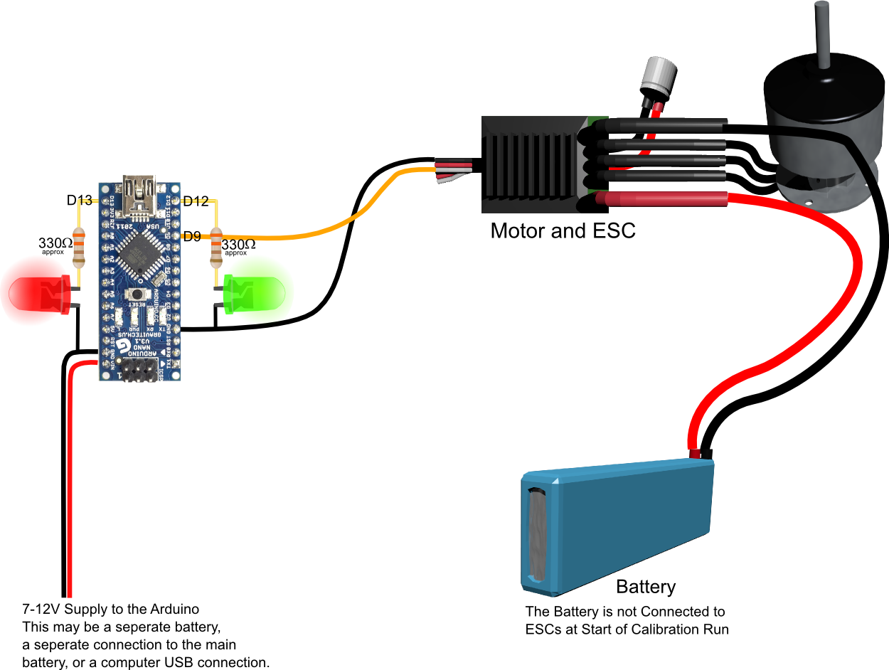
For the circuit, the two LEDs are on pins 12 and 13, with resistors of about 560 ohms or 220 ohms. Pin 9 is connected to the ESC signal line. All ground lines are connected together.
In order to get a tone from the ESC a motor must be connected. After all that is what is making the sound.
The circuit is shown below.
 Click here to get a higher resolution version.
The sketch below can be downloaded from here: ESCcalibrator.ino
/* ESCcalibrator.ino
The ESCs used in the ROV will need to be calibrated to the Arduino
output signals.  For most ESCs the method of programming them is
to put the transmitter to maximum throttle, turn on the ESC and
wait for it to signal that it has the maximum setting calibrated,
then put the throttle to minimum and wait for the ESC to signal
that it has the minimum setting calibrated.
This sketch will provide the throttle motions and signal the shift
to the low setting by flashing a red LED.  A flashing green LED
will signal the end of the process.

The connections are:
7.6V onto the ESC when needed.
Servo control pin for ESC on Arduino pin D9
Red LED on Pin 13
Green LED on Pin 12

*/

#include <Servo.h>
Servo ESC;  //Servo object called "ESC"
int throttle = 0;  //Variable for the throttle setting.
const int grnLEDpin = 12;
const int redLEDpin = 13;


void setup()
{
  pinMode(grnLEDpin,OUTPUT);
  pinMode(redLEDpin,OUTPUT);
  ESC.attach(9,600,2250); //attach the ESC to pin 9
  //Due to problems with the ESC recognising the maximum
  //position at the default settings, the figures after
  //the pin number are the microsecond signals for the
  //minimum and maximum that the ESC will recognise.
  // 600 and 2250 work.
  throttle = 180;  //Set the throttle to maximum
  ESC.write(throttle); //Set the ESC signal to maximum
  //At this point the ESC's power should be connected.
  delay(10000);  //Allow the user time to connect the battery to
  //the ESC.
  redBlink();  //Jump to the Blinking red LED subroutine
  throttle = 0;  //Set the throttle to zero
  ESC.write(throttle);  //Set the ESC signal to the zero position.
  delay(10000);  // allow a 10 second delay for the ESC to signal
  //that it is done.
  throttle = 90;  //Set throttle to the neutral position.
  ESC.write(throttle);
  delay(10000);   //The ESC should now be calibrated.
}

void loop()
{
  //Blink the green LED to signal end of process
  digitalWrite(grnLEDpin, HIGH);
  delay(1000);
  digitalWrite(grnLEDpin, LOW);
  delay(1000);
}

void redBlink()
{
  //Blink the redLED to signal the imminent move to the
  //low throttle setting.
  for(int i = 1; i < 6; i++)  //do the sequence for 10 seconds.
  {
    digitalWrite(redLEDpin, HIGH);
    delay(1000);
    digitalWrite(redLEDpin, LOW);
    delay(1000);
  }
}