Calibrating the ROV's ESCs
For the ROV project due to a change in the ESCs used for that project this page has been superceded and is here for historic reasons only.
Please see the article on programming and calibrating the HobbyWing EZRUN 18A Car ESC here: Programming and Calibration the EZRUN 18A ESCs
This page describes a step in initialising the ROV that was initally planned to be built into the standard operating program. The sketch outlined below calibrates all of the HobbyKing 10A Brushless ESCs in one hit based on the state of a jumper on the board. If the jumper is closed then a calibration run is required, if the jumper is open then the ROV will run normally. The reason for choosing the jumper to be closed to signal a calibration run is so that the ROV will run if the jumper has been lost.
To calibrate any of the ESCs that I have ever encountered they follow a common sequence of throttle settings. For aircraft ESCs the sequence is; supply electricity to the ESC when the throttle is in the full power position, then throttle back to zero power position. For ground based ESCs with a reverse, the sequence is; supply electricity to the ESC when the throttle is in the full power position, then move the throttle to the full reverse power position, then set the throttle to the neutral position. Because the ROV makes use of car ESCs with reverse the sketch has been designed to follow the latter sequence.
The ESC calibration sequence is the same as described in the ESC Calibration Using an Arduino article although the flashing LED signals are different. In this the red LED flashes initially to tell the user to plug in the main ROV battery to supply power to the ESCs. Power for the Arduino is supplied independently for this process. As the ESCs are connected to their motors, the signals the ESCs sounds using the motors are used to confirm the successful implementation of each step in the calibration sequence. The ESCs signal successful completion by beeping the number of battery cells detected (3 in the case of the 3S LiFePo batteries being used in the project) and then playing their little scale. At this stage power can be removed from the system and the jumper set to open.
If the ESCs beep continuously, this means it they are not detecting the maximum throttle signal. Make sure they is all connected correctly. If they are, then you may need to change the signal pulse widths for the minimum and maximum throttle positions. This is done through the attach command as shown below and in the sketch.
ESC.attach(9,600,2250);
This says that an ESC is going to be attached to pin 9. The minimum throttle signal is a pulse width of 600 microseconds and the maximum throttle pulse width is 2250 microseconds. The defaults if not defined are 544 microseconds and 2400 microseconds respectively.
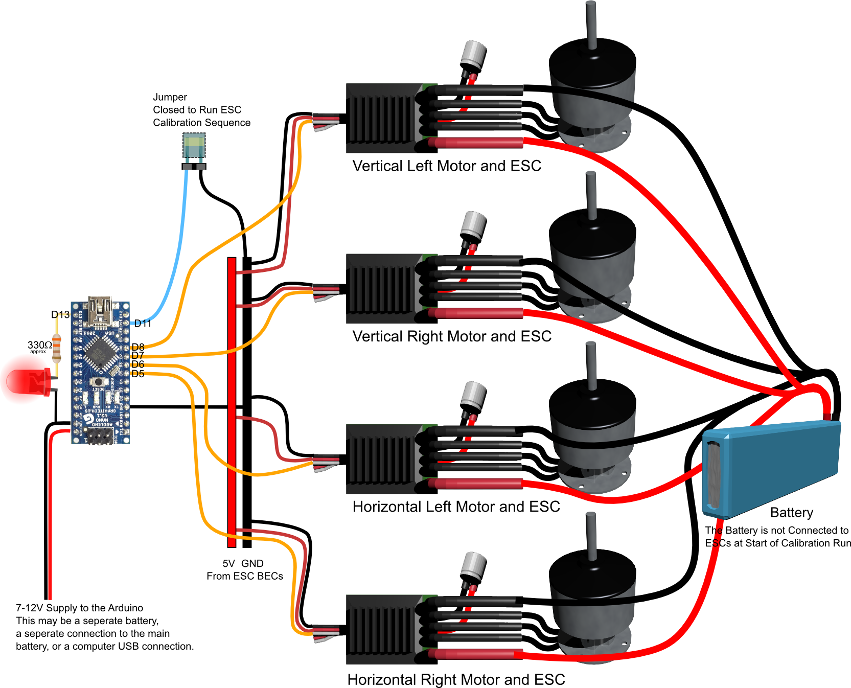
The Circuit
The Circuit for this is shown below. These are the same pin assignment as is used in the full ROV circuit.
 Click here to get a higher resolution version.
The pin assignments
- D13 = RED LED pin.
- D11 = Jumper pin
- D5 = ESC Horizontal Right
- D6 = ESC Horizontal Left
- D7 = ESC Vertical Right
- D8 = ESC Vertical Left
The sketch for this operation
The sketch below can be downloaded from here: ROVSubBv0.ino
/*
ROVSubBv0.ino
This sketch is designed to calibrate all of the ESCs
simultaneously.  In theory this will only need to be
done once on a new rig, but in order to allow it to
be repeated, it is intended that this sketch be included
with the main sketch and be triggered by a jumper being
closed.  In this sketch, if the jumper is open then the
calibration is not performed and the sketch will initialise
the ESCs at their neutral point as per normal operation, then
just do a limited low speed sweep.

The procedure is;
1. With everything off, put the jumper across the header
provided. Under normal operations the jumper is OPEN so
that if the jumper is lost the ROV can still run.
2. Apply 7-12V power to the Arduino only (via the JST connection)
to the board.  The Arduino will start and initialise its settings
on the ESC control pins.
3.  The Arduino will blink the RED LED on the control board for
10 seconds during which time a battery can be connected to the
main battery terminals.
4.  The Arduino will supply the ESCs with the preset sequence of
control inputs to calibrate them.
5.  Once that is done calibration is complete and the battery can
be disconnected, the jumper opened, and the control board power
JST returned it its usual connection with the main battery supply.
Depending on the ESCs this will typically be signalled by the
ESCs using the motors to make a sound or tune.  To signal the end
of the process the red LED will be blinked fast.


The pin assignments are;
  * D13 = RED LED pin.
  * D11 = Jumper pin
  * D5 = ESC Horizontal Right
  * D6 = ESC Horizontal Left
  * D7 = ESC Vertical Right
  * D8 = ESC Vertical Left

Please note that the ESCs will all have been programmed by this
point in the project.
*/

#include <Servo.h>

Servo ESCVL;  // Create Servo Object ESC Vertical Left
Servo ESCVR;  // Create Servo Object ESC Vertical Right
Servo ESCHL;  // Create Servo Object ESC Horizontal Left
Servo ESCHR;  // Create Servo Object ESC Horizontal Right

const int RedLEDpin = 13; // The indicator LED pin is 13.
const int CalJumper = 11; // The ESC Calibration jumper is on pin 11

int throttle = 0;  //variable for the throttle setting that will
                   // be send to each ESC.

void setup()
{
  pinMode(RedLEDpin,OUTPUT);
  pinMode(CalJumper,INPUT);
  digitalWrite(CalJumper,HIGH); //Turn on internal pullup on Jumper Pin
  ESCVL.attach(8,600,2250); //attach the ESCVL to pin 8
  ESCVR.attach(7,600,2250); //attach the ESCVR to pin 7
  ESCHL.attach(6,600,2250); //attach the ESCHL to pin 6
  ESCHR.attach(5,600,2250); //attach the ESCHR to pin 5
    //Due to problems with the ESC recognising the maximum
    //position at the default settings, the figures after
    //the pin number are the microsecond signals for the
    //minimum and maximum that the ESC will recognise.
    // 600 and 2250 work.


  if(digitalRead(CalJumper) == LOW)  //The Jumper is bridged to indicate that
  {                    //a calibration run is required.  If it is open
                       //the sketch should jump to the Loop().
    throttle = 180;  //Set the throttle to maximum
    ESCVL.write(throttle); //Set the ESCVL signal to maximum
    ESCVR.write(throttle); //Set the ESCVR signal to maximum
    ESCHL.write(throttle); //Set the ESCHL signal to maximum
    ESCHR.write(throttle); //Set the ESCHR signal to maximum
    for(int t = 1; t < 6; t++)  //do the following secquence for ten seconds
    {
      Blink(1000); //Call the Blink function with a long blink period.
    }
    throttle = 0;  //Set the throttle to zero
    ESCVL.write(throttle);  //Set the ESCVL signal to the zero position.
    ESCVR.write(throttle);  //Set the ESCVL signal to the zero position.
    ESCHL.write(throttle);  //Set the ESCVL signal to the zero position.
    ESCHR.write(throttle);  //Set the ESCVL signal to the zero position.

    delay(10000);  // allow a 10 second delay for the ESCs to signal
     //that it is done.
    throttle = 90;  //Set throttle to the neutral position.
    ESCVL.write(throttle);  //Set the ESCVL signal to the neutral position.
    ESCVR.write(throttle);  //Set the ESCVL signal to the neutral position.
    ESCHL.write(throttle);  //Set the ESCVL signal to the neutral position.
    ESCHR.write(throttle);  //Set the ESCVL signal to the neutral position.

    delay(10000);   //The ESC should now be calibrated.
  }
  else
  {
    throttle = 90;  //Set throttle to the neutral position.
    ESCVL.write(throttle);  //Set the ESCVL signal to the neutral position.
    ESCVR.write(throttle);  //Set the ESCVL signal to the neutral position.
    ESCHL.write(throttle);  //Set the ESCVL signal to the neutral position.
    ESCHR.write(throttle);  //Set the ESCVL signal to the neutral position.

    delay(10000);   //Ten second delay
    //The ESC should now be initialised and ready to run.
  }
}


void loop()
{
  if(digitalRead(CalJumper) == LOW)  //The Jumper is bridged
  {
    //Game Over.
    Blink(200);  // Call the Blink function with a fast blink time
  }
  else
  {
    //If the jumper is open then do a sweep sequence in both
    // forward and reverse directions with a 5 second wait
    // between direction changes.
    for(throttle = 90; throttle < 105; throttle ++)
    {
      ESCVL.write(throttle);  //Set the ESCVL signal to the throttle.
      ESCVR.write(throttle);  //Set the ESCVL signal to the throttle.
      ESCHL.write(throttle);  //Set the ESCVL signal to the throttle.
      ESCHR.write(throttle);  //Set the ESCVL signal to the throttle.
      delay(15);
    }
    for(throttle = 105; throttle >= 90;throttle -=1)
    {
      ESCVL.write(throttle);  //Set the ESCVL signal to the throttle.
      ESCVR.write(throttle);  //Set the ESCVL signal to the throttle.
      ESCHL.write(throttle);  //Set the ESCVL signal to the throttle.
      ESCHR.write(throttle);  //Set the ESCVL signal to the throttle.
      delay(15);
    }
    delay(5000);
    for(throttle = 90; throttle >= 75; throttle -=1)
    {
      ESCVL.write(throttle);  //Set the ESCVL signal to the throttle.
      ESCVR.write(throttle);  //Set the ESCVL signal to the throttle.
      ESCHL.write(throttle);  //Set the ESCVL signal to the throttle.
      ESCHR.write(throttle);  //Set the ESCVL signal to the throttle.
      delay(15);
    }
    for(throttle = 75; throttle < 90; throttle +=1)
    {
      ESCVL.write(throttle);  //Set the ESCVL signal to the throttle.
      ESCVR.write(throttle);  //Set the ESCVL signal to the throttle.
      ESCHL.write(throttle);  //Set the ESCVL signal to the throttle.
      ESCHR.write(throttle);  //Set the ESCVL signal to the throttle.
      delay(15);
    }
    delay(5000);
  }
}

void Blink(int period)
{
  //A function to blink the RedLED at varying speeds based on 'period'
  digitalWrite(RedLEDpin, HIGH);
  delay(period);
  digitalWrite(RedLEDpin, LOW);
  delay(period);
}