Bread and Yoghurt Brewing Temperature Controller

For many years I have been making all the bread we use in our household and brewing our own perpetual heirloom yoghurt. Of course, for both these activities you need a warm space to keep the bugs happy. To do this I used an old 12V battery charger and the heated printer bed we used as a duckling warmer. A simple temperature controller was put between the battery charger and heated bed to maintain the right temperatures. This worked pretty well until the day the battery charger finally gave up the ghost with a bang, flash of light and issuing of that ever important smoke that keeps everything electronic working. The solution was simple; get another 12V supply and continue. But it wasn’t to be. I found to my amazement that the temperature controller we had used would not work on clean DC as supplied by a modern 12V power supply or even from a battery. It only worked on the rectified and un-smoothed 12V provided by the cheapest, nastiest 12V supplies that were now impossible to find.
All of a sudden I had another emergency electronics project on my hands. And so I devised a scheme to build a better quality temperature controller based on an Arduino. Alongside this was the introduction of a new heater arrangement that would provide more even and effective heating.
The Circuit
In many ways the project was a cut down version of the Solar Water Heater Controller Project making use of many of the same components such as the same opto-coupled relay and thermistors. The controls consisted of two potentiometers to set the upper and lower set point temperatures, a push button to switch between selecting the set points and monitoring the temperature. A 4-digit display showed the current temperature and two LEDs above each of the potentiometers indicated which set point you were setting. I wanted to keep it as simple as possible.
I used the shell of the old battery charger to house the circuit and so had an ammeter and switch available to use.
The 12V supply was from a 6A 12V DC supply normally used to power arrays of LED downlights. With a 40W heater the maximum current was going to be just over 3A and so I had plenty of capacity with this power supply.
The four digit display was one based on two 74HC595 shift registers rather than the much more convenient TM1637 display.
The major components used were:
- Arduino Uno
- Opto Coupled Relay
- LM317 Voltage regulator providing 5V supply to some components
- A 10k NTC Thermistor with a Beta value of 4100
- 12V 6A LED Driver
- 4 Bit LED Digital Tube Module (based on two 74HC595 Shift Registers). I purchased this from Banggood.
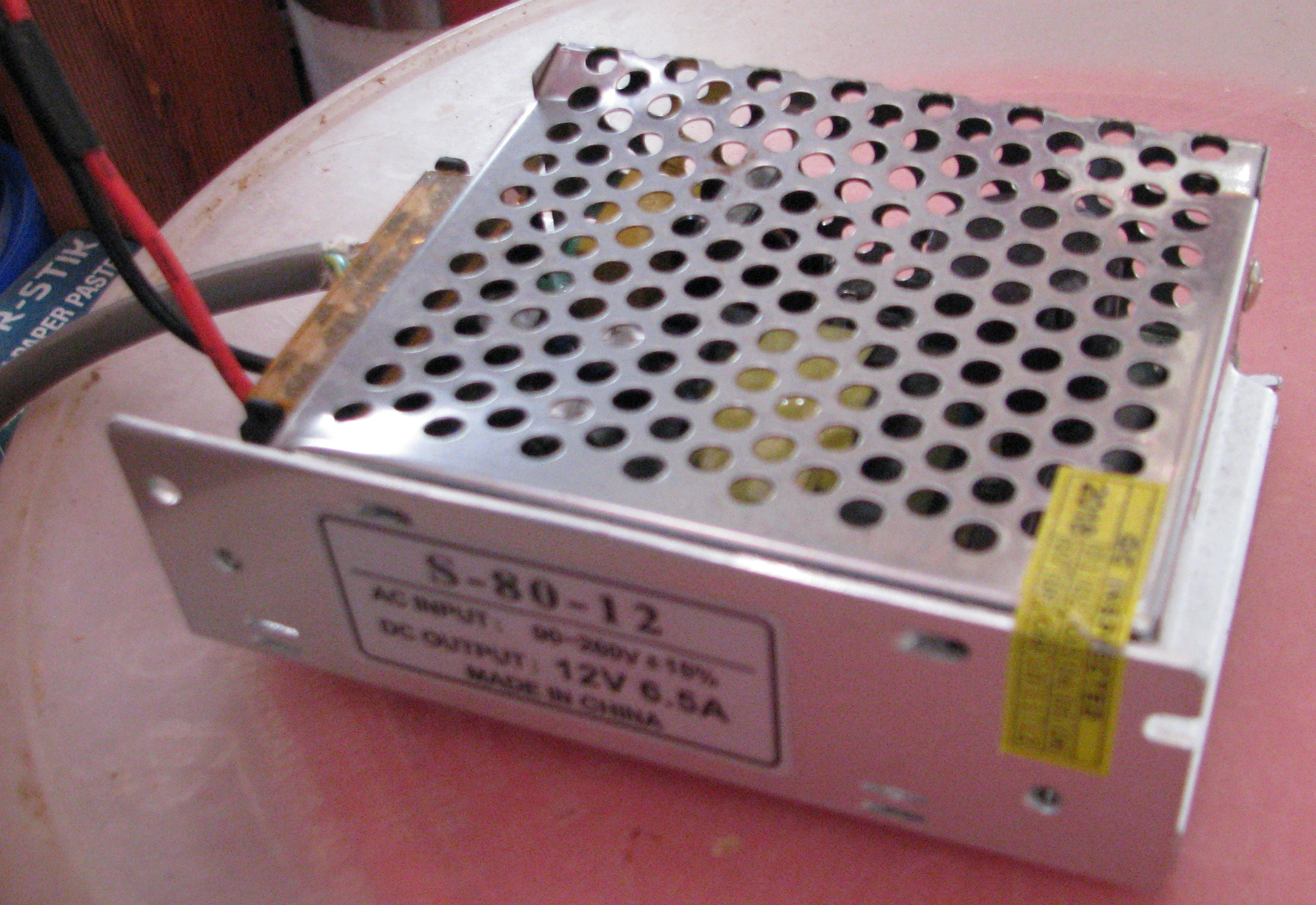
The Power Supply
The Physical Connections
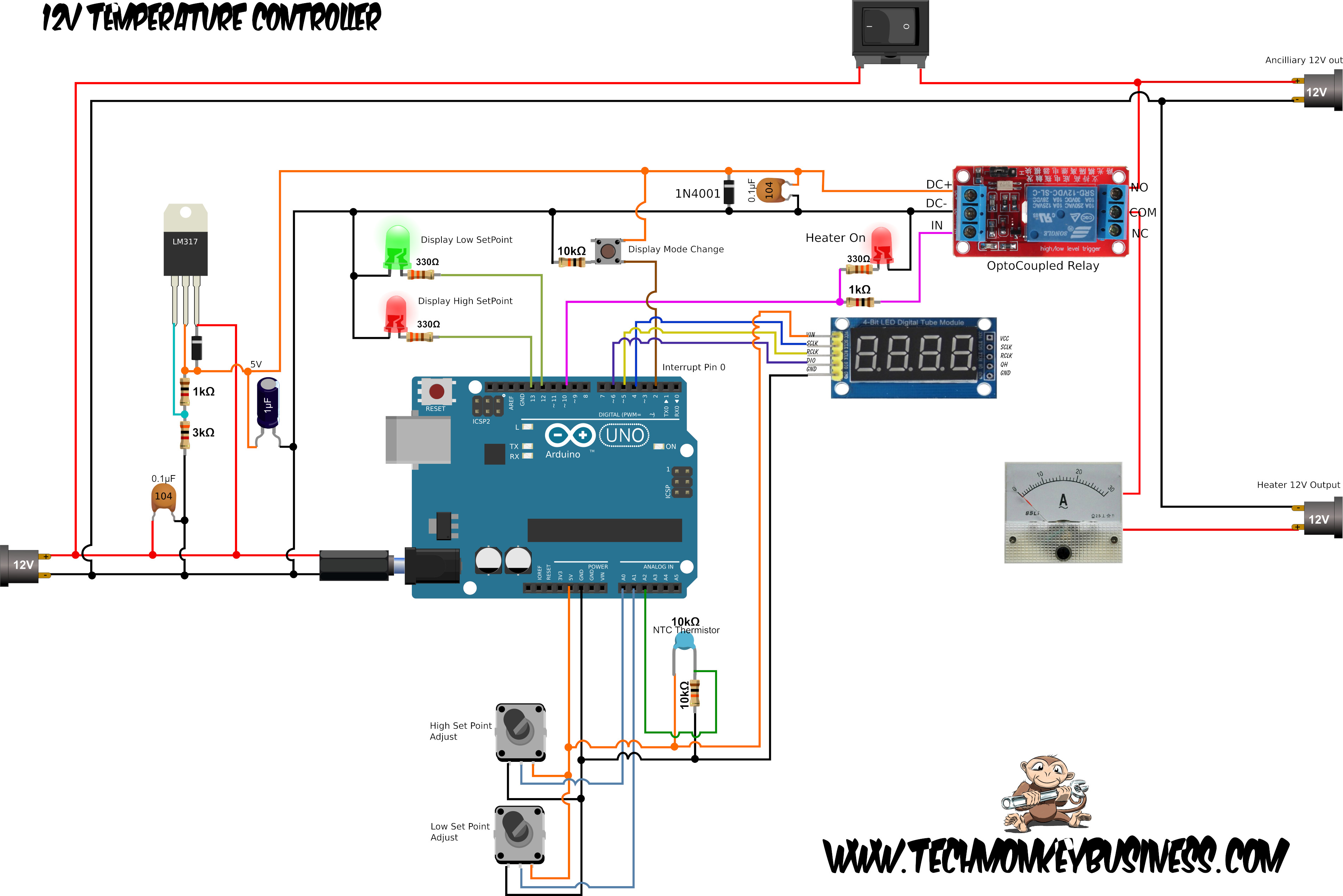
The diagram below shows how the circuit was constructed. I had an Arduino Uno and shield style prototyping board handy so I grabbed these for the main part of the circuit. The whole lot was stuffed into the battery charger casing. If you think the diagram below is messy, it’s nothing compared to the mass of wires and bits that ended up being shoved into the battery charger casing.

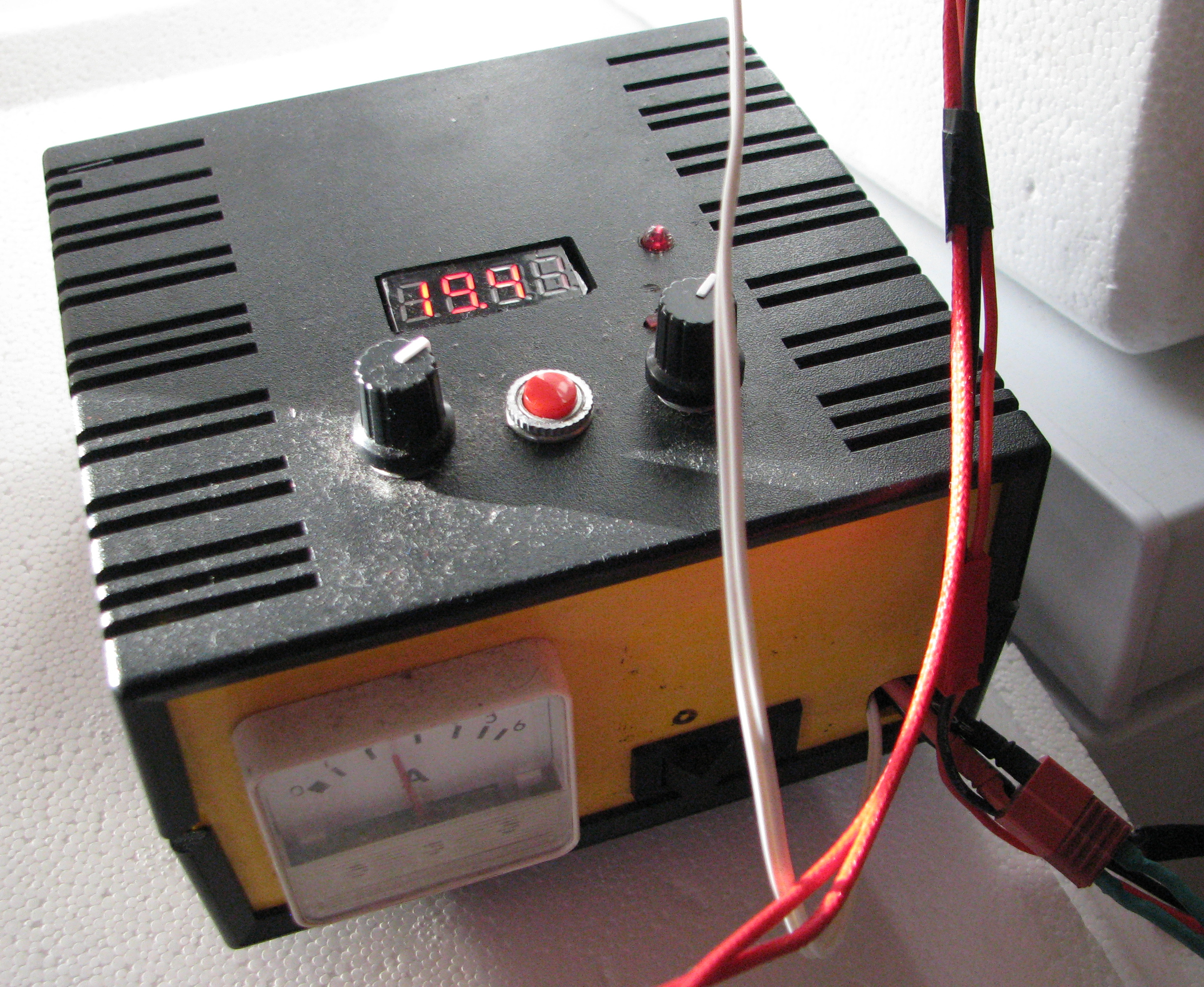
The Controller Mounted in Old Battery Charger Shell
The Code
You can download the code from here: TempControlv6.ino
You will need the LEDDisplay74HC595 library to use the 4-Digit display. You can find that on Chrizzzzz’s official repository or here on TechMonkeyBusiness or through the Collected Arduino Libraries page.
To keep things simple I used a couple of work arounds:
- I have avoided using interrupts to monitor the button because of the problems caused by button bounce. Instead the user has to hold the button down for a short period in order to change modes between displaying the temperature and setting the temperature set points.
- I also included an limit on the temperature set points to ensure the upper set point was always a little above the lower set point and visa versa.
/* TempControlv6.ino
This is a temperature controller for low temperature operation of
a low temperature heating device.  The temperatures are measured by
a 10K B=4100 Thermistor with setpoints selected by using two potentiometers.
The setpoints, and current temperature are shown on a 4 dgit display.
A button is used to select between what is shown and what is changable.
LEDs indicated which setpoint is being shown and changable and another LED
shows when the relay is closed.

Hamish Trolove 2020

4-Digit display is one using two 74HC595 shift registers.

The relay is an optically isolated module rated for 10A.

Supply is 12V, but board mounted regulator outputs 5V for
the 4-digit display, and Relay solenoid.

Pins are:

A0: High set point adjust potentiometer
A1: Low set point adjust potentiometer
A2: 10K B=4100 Thermistor

D2 (interrupt 0): Button for selecting display mode

D4: 4 Digit Display SCLK
D5: 4 Digit Display RCLK
D6: 4 Digit Display DIO

D10: Relay control (IN)
D11: Relay ON LED
D12: Low Setpoint Display Model indicator
D13: High Setpoint Display Model indicator

*/

#include <LEDDisplay74HC595.h>  // For the 4-digit diplay
#include <math.h>  // We need this to calculate temperature values from

const int buttnPin =2;

const int sclkPin = 4;
const int rclkPin = 5;
const int dioPin = 6;

const int RelayPin = 10;
const int RelayLEDPin = 11;
const int LEDDisplaySPL = 12;
const int LEDDisplaySPH = 13;

const int SetPointH = A0;  // The set point potentiometers
const int SetPointL = A1;
const int ThermPin = A2;  // The thermistor on Analogue Pin 2

LEDDisplay74HC595 ledDisplay(sclkPin, rclkPin, dioPin);


int ThermValue = 0;  //The raw thermistor analog pin reading
double TempAct = 0.0; //Actual Temperature
double TempSPL = 0.0; //Temperature Set Point Low
double TempSPH = 0.0; //Temperature Set Point High
double Temp2Disp = 0.0; //Temperature to Display

int TempSPLraw = 0; //Raw analog reading for Low Temp setpoint
int TempSPHraw = 0; //Raw analog reading for Low Temp setpoint

long runprevMillis = 0;  // will store last through cycle
long runInterval = 500;  //Cycle time between readings

int DispID = 1; //Pointer for which item is shown on display, 0 = Low Set point
                // 1 = Actual temp, 2 = high set point.

boolean LEDSPHFlag = LOW; //Flags for the Display Status LEDs
boolean LEDSPLFlag = LOW;


void setup()
{
  pinMode(RelayPin,OUTPUT);
  pinMode(RelayLEDPin, OUTPUT);
  pinMode(LEDDisplaySPL,OUTPUT);
  pinMode(LEDDisplaySPH,OUTPUT);
  pinMode(buttnPin,INPUT);

  //Do an initial read of the setpoint potentiometers
  TempSPLraw = analogRead(SetPointL);
  TempSPHraw = analogRead(SetPointH);
  TempSPL = 0.01*float(map(TempSPLraw,0,1023,1500,5500));
  TempSPH = 0.01*float(map(TempSPHraw,0,1023,1800,6000));
  if(TempSPL > TempSPH-2.0)
  {
    TempSPL = TempSPH-2.0;  //This prevents the lower setpoint
          //being greater than the upper setpoint
  }
  if(TempSPH < TempSPL+1.5)
  {
    TempSPH = TempSPL+1.5;  //This prevents the upper setpoint
          //being lowerer than the lower setpoint
  }


  digitalWrite(RelayPin,HIGH); //Start of with the relay ON
  digitalWrite(RelayLEDPin,HIGH);

}

void loop()
{
  unsigned long RuncurrentMillis = millis();
  if(abs(RuncurrentMillis - runprevMillis > runInterval))  // absolute value used to get around
  //problem caused by long numbers overrunning if systems operates for longer than 50 days.
  {
    runprevMillis = RuncurrentMillis;  //Save the last time through
    ThermValue = analogRead(ThermPin);
    TempAct = TempCalc(ThermValue);  //Just duck out to the calculation routine.

    if(digitalRead(buttnPin))
    {
      DispID = DispID+1;
      if(DispID > 2)
      {
        DispID = 0;
      }
    }

    if(DispID==0)
    {
      LEDSPHFlag = LOW;
      LEDSPLFlag = HIGH;
      TempSPLraw = analogRead(SetPointL);
      TempSPL = 0.01*float(map(TempSPLraw,0,1023,1500,5500));
      if(TempSPL > TempSPH-2.0)
      {
        TempSPL = TempSPH-2.0;  //This prevents the lower setpoint
        //being greater than the upper setpoint
      }
      Temp2Disp = TempSPL;
    }
    else if(DispID==1)
    {
      LEDSPHFlag = LOW;
      LEDSPLFlag = LOW;
      Temp2Disp = TempAct;
    }
    else
    {
      LEDSPHFlag = HIGH;
      LEDSPLFlag = LOW;
      TempSPHraw = analogRead(SetPointH);
      TempSPH = 0.01*float(map(TempSPHraw,0,1023,1800,6000));
      if(TempSPH < TempSPL+1.5)
      {
        TempSPH = TempSPL+1.5;  //This prevents the upper setpoint
        //being lowerer than the lower setpoint
      }
      Temp2Disp = TempSPH;
    }

    digitalWrite(LEDDisplaySPL,LEDSPLFlag);
    digitalWrite(LEDDisplaySPH,LEDSPHFlag);


    if(TempAct<TempSPL)
    {
      digitalWrite(RelayPin,HIGH);
      digitalWrite(RelayLEDPin,HIGH);
    }
    else if(TempAct>TempSPH)
    {
      digitalWrite(RelayPin,LOW);
      digitalWrite(RelayLEDPin,LOW);
    }
  }
  ledDisplay.refresh(Temp2Disp, 2);  //Display the temperature to 2 decimal places

}


double TempCalc(int ThermIn) //For Thermocouples Tin and Tstag with beta values 4100
{
  double TempVal = 1/((1/298.00)+(1/4100.00)*log(1024.00/ThermIn-1.00));
  TempVal = TempVal - 273.00;  //Note the extra decimal places force float usage.
  return TempVal;
}
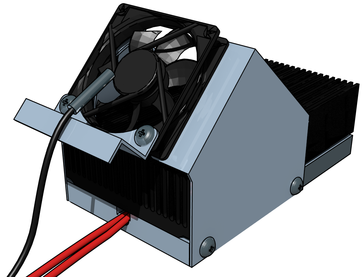
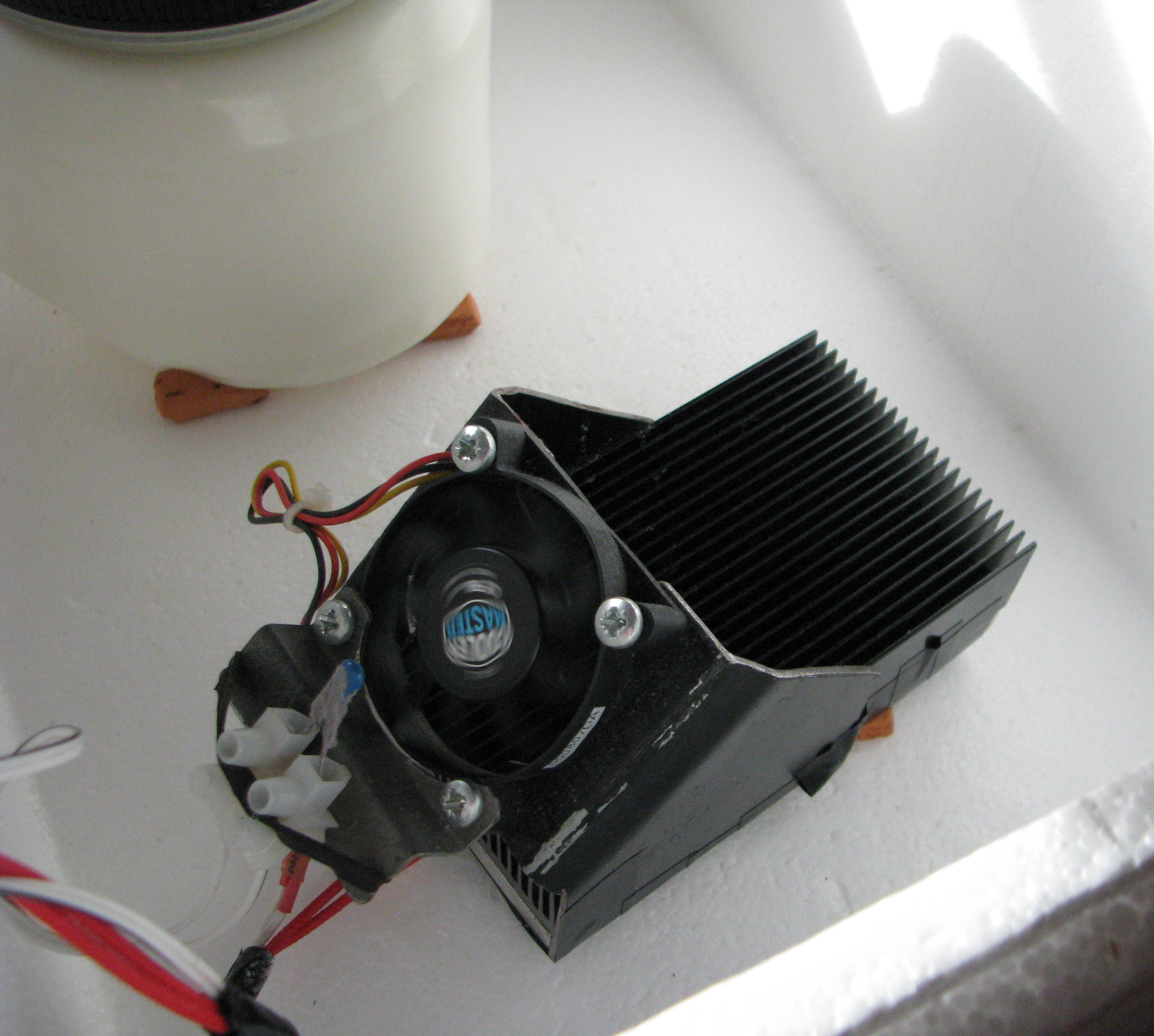
The Heater
The heater was a 40W 3D Printer cartridge heater which was fitted into a block of aluminium to which a massive heatsink was screwed. Across this a repurposed 12V computer CPU fan blows air. This arrangement was extremely effective at transferring the heat from the heater element to the air. So much so that even if the fan and temperature control circuit failed the heater element would never get much above 50°C.
The temperature sensor was mounted on the intake to the fan.
To make sure there is no chance of overheating I sit the heater on four ceramic mini-bricks.
The specs for the heat sink were:
- Size: 120 x 69 x 27mm
- Plate thickness: 27mm
- Tooth slice thickness: 1mm
- Tooth spacing: 2.5mm
- Tooth piece quantity: 22
The heater sitting in a repurposed polystyrene packing box keeping a yoghurt warm.
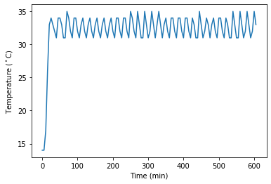
How does it perform?
Pretty good. The temperature cycles between the two set points nicely. The graph appears to show a variation but this is simply due to the five minute sample resolution missing the peaks and troughs. If some thing like a warm dough or a cool yoghurt starter is put into the polystyrene box you see the time to heat change as it needs to do more or less work to get the load to temperature.
The temperature logger I used was Elfnor’s Pyboard-based data logger connected to a digital humidity and temperature sensor.


The described project is provided by Hamish Trolove under a Creative Commons Attribution 4.0 International License.