An Arduino Based Solar Water Heater Controller
You can download the complete notes for this project in a pdf form from here: SWHController_Article.pdf

An Emergency Project
So we got back from our Christmas/New Year break to find our water cylinder temperature was somewhat colder than we would have expected. Normally when we go away for a period, the solar water heater gets the water up to a very high temperature even during times during which the weather is a bit variable. Although this summer has been pretty rubbishy the low temperature immediately had me suspicious that something was not right. This was soon confirmed when night fell and the solar water heater circulation pump continued to operate.
As it turned out a power-spike or something had gone through the house while we were away and scrambled the solar water heater controller’s brains. It now thought that even 25°C days were too cold and needed the pump turning over for frost protection. So I quickly put a timer in between the controller and the wall socket and set it so that it would only run during daylight hours.
The existing controller is a Solastat controller from Senztek. I can’t say it was the best controller, and had some annoyingly inappropriate set points for the onset of frost protection. This had frost protection beginning when the ambient conditions were 8°C. Wellington often gets cold days around 8°C, but it very rarely gets below freezing. So this wasted a lot of hot water. I tried to get information from Senztek about adjusting the settings (which can be done), but they would not release the method for unlocking the device and basically were very unhelpful. So, for a few years my to-do list featured a project to replace the controller with something that could be set for the local conditions. This failure of the Solastat was the perfect opportunity to put it into action and design, build, program, install, and commission a much smarter Solar Water Heater Controller in which the set points could be optimised for the local conditions.
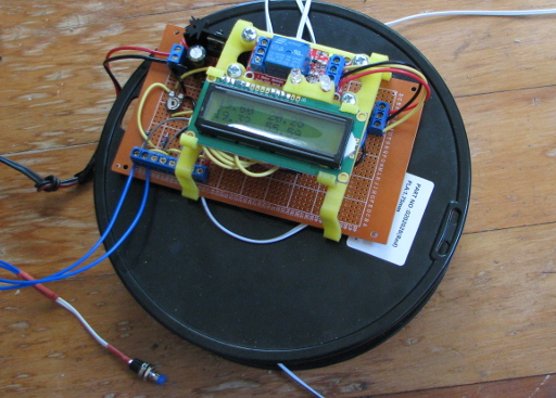
The New Controller Being Tested
The Project
Designing the electronics and logic was a relatively smooth and pain-free process. Installing it and dealing with real-world stuff was not. Below you will find links to articles where I describe the idealised system that would run very well if you have good reliable temperature sensors and you have the ability to put the sensors exactly where you want them. I also describe the actual system as it was installed and the adjustments and compromises made to get it to work nicely.
You will find the logic flow diagrams, arduino programs, circuit diagrams, and perf-board layouts for each system.
The Idealised System
In the perfect world of design and programming, sensors are shiny and accurate, noise in the system does not exist, and the system always has the perfect spot to install your sensors.
Here is the article on the controller for the perfect world. Perfect World Solar Water Heater Controller.
The Actual Installed System
In the real world, things are a bit more gritty. Your sensors do not agree perfectly, electric motors, relays, and other stuff throw messy electrical stuff everywhere, the plumbers have created a unholy mass of brass fittings on the solar water heater that make it hard place the sensors where they will be capturing the best data. The hot water cylinder does not have a nice convenient sensor pocket, and broken sensor wires happen too easily. Nuff said?
Here is the article on the controller for the real world. Real World Solar Water Heater Controller.
The Casing and Internal Supports
The circuit board was built up on a 9cm x 15cm perf-board (30x48 holes) and the LCD screen for displaying the data was connected to the main board through a number of wires which meant it could be positioned relatively freely. This meant the whole lot could be conveniently installed in a UB2 ABS Jiffy Box as supplied by Jaycar. These are a nice sturdy box with an internal volume of 172mm x 104mm x 57mm.
Because I wanted to be able to access the controller Arduino relatively easily to load new variations of the program while optimising the set points, the case needed to the lid to lift off without having the LCD screen or LEDs attached to it. A 3Dprinted frame was designed to carry the LCD screen, LEDs, and relay so they would remain in position when the cover was removed. Two feet were also designed to match the curve of the hot water cylinder surface and hold a series of magnets. In theory the magnets would have held the controller to the cylinder but in reality they weren’t quite strong enough and duct tape was employed to help hold it in place.
Chances are though, if you are looking at this project, you are probably going to have a different size hot water cylinder, have made different choices about the relay module to use, different size box, and a whole host of other things that mean the structure you will require will be different from what I have used. For the sake of completion though, here are the relevant files for designing and 3D printing the support arrangement.
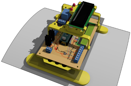
Blender File. The Blender file was designed in Blender 2.58. Some of the components used have come from the collection of components I have on this webpage:Component model Library.
You can download the .blend files here: SWH_Controller_Frame-blend.zip
The STL files for 3D printing can be found here: SWH_Controller_Frame-STLs.zip
Optimising the Device - What to Tweak
Control Set Points
Once the device is up and running there is always room for optimising the set points to the local conditions and the actual performance of the temperature sensors. As mentioned already, Wellington gets cold but very rarely freezes. This means we can keep the frost protection related set points relatively close to 0°C without risking patches of the panel freezing.
The other factor that needs to be accounted for is the error between the actual temperature you are trying to read and the temperature the sensor sees. In the case of the system here, the solar water heater outlet temperature sensor is installed in a small pocket projecting into the flow near the outlet of the solar water heater. It gets good measurements when the water is flowing but when the pump is off, the heat has to travel through the metal fittings before it gets to the sensor. Because of this, the sensor can be slow to detect the water temperature in the panel reaching a suitable temperature to begin pumping. When the pump starts, this leads to a sudden temperature rise at the sensor when the heated water reaches it.
Observing the temperatures into and out of the solar water heater as well as the temperature difference between the solar water heater outlet and the cylinder intake during steady pumping and when the pump starts will allow the user to make an educated guess about what the appropriate set points might be. My current settings are: 2.5°C between the solar water heater outlet and the intake to the hot water cylinder, while to turn the pump off the temperature differential between these same two sensors must get below 1.5°C. This seems to give a good hot water yield and responds well to less sunny days and the low sun angles of early morning and late afternoon.
The set points are defined by the following variables; FrostTemp, SWHFrostThresh, SWHOutHeatedTemp, SWHCylTdiff, and SWHTdiff.
Look for the following lines in the control sketches.
double FrostTemp = 4.00; //Temperature below which Frost is a risk.
                      //Adjust for local conditions.
double SWHFrostThresh = 5.00; //Temperature at SWH at which pump
                      //will start if running in Frost protection mode.
double SWHOutHeatedTemp = 8.00; //Temperature which will indicate that
                      //hot water is in SWH for frost protection.
double SWHCylTdiff = 2.50; //Temperature difference between cylinder
                      //and solar water heater before pumping starts.
double SWHTdiff = 1.50;  //Min temperature difference between cylinder
                      //and solar water heater before pumping is stopped.
SWHCylTdiff, and SWHTdiff are the two set points that control the operation of the solar water heater pump during normal operations. Both refer to the temperature difference between the solar water heater panel outlet and the sensor location at the hot water cylinder intake.
On my system, I have observed that there is a difference in the readings between the solar water heater inlet and the solar water heater outlet in the early hours of the morning when they should be pretty much the same. Likewise there is a small but consistent difference between what the “Stagnation temperature” sensor is reading and what the nearby home weather station temperature sensor is reading. Unfortunately I was unable to have a time when I could calibrate the sensors together, but the presence of these differences makes me err on the side of caution when it comes to the set points for frost protection. With a bit more testing as autumn and winter approaches I am likely to be able to refine the frost protection set points to reflect actual conditions better.
Sensor Calibration
Before attempting to install the solar water heater controller, the idealised system had four thermistors that were supposedly 10kΩ NTC type with a Beta Value of 4100K. Generally it is not so important that the temperature they report is absolutely accurate, but agreement between the sensors makes life much easier. To test this it is worth putting all of your sensors in a glass of water (not touching the side) or on some surface that has an even temperature across it, and seeing what temperatures are reported. When I did this I found that one of the sensors had a permanent offset from the other three sensors. By changing the temperature of the water across a wide range, I was able to generate an expression to adjust the reading from this particular thermistor to a temperature that would match the others.
Carrying out a test like this is relatively simple when you have the circuit built, and reporting to the LCD screen.
Of course, the fact that I used the thermistors already installed on the system in the final version of this system meant that I was not able to achieve such a good match between the different sensors. This is reflected in a greater uncertainty in, and more fiddling of, the set points.
Things to watch out for
There are several things I have learned from this system so far;
Check your sensors are reading pretty much the same. As alluded to above, having good agreement between your sensors makes life a whole lot simpler.
The LCD screen I used is very sensitive to electrical noise. Despite all the careful arrangements of capacitors, flyback transistors, opto-isolation, and pumps with their own noise suppression circuits, the LCD screen still spends a bit of its time displaying garbage when the relay opens. Just because the display is haywire does not mean the system has failed. The rest of the system is working perfectly fine. I have not bothered to try out some of the alternative screens such as the i2c version or just a simple four digit LED display. I just ignore the problem and sooner or later the display comes back. Damn thing!
This project deals with 240V. Watch where you’re sticking your mitts. Even better make sure it is unplugged when you are fiddling with it.
The pump override switch requires the user to hold the button in for a period of before it will start. This is because of the “debounce” process used to guard against short cycling the pump. It is not a problem, just something for the user to be aware of.
Operation
The weather this “summer” has been really weird. This has been great for testing the solar water heater controller! It has had some really cold days to look at followed by some stinking hot ones, followed by dull days when the temperature in the hot water cylinder is still very high from the previous day’s solar harvest, and also a few quite variable days where the cloud comes and goes. The solar water heater controller had responded as expected to all of these conditions and successfully given us good hot water without losing any due to inappropriate pumping when the incoming solar heat was not hot enough to provide any benefit to the water. That is what I call a success.
Update September 2017
The solar water heater controller has been running for seven months now without a glitch. It has dealt with freezing temperatures, power failures and voltage spikes from the local electrical supply. We have had many adverse weather events to knock and still the solar water heater controller has dutifully run the pump when there is advantage in doing so. I am well pleased with how it has performed through the winter and how it has survived the power system failures.
Update February 2019
The solar water heater controller has been running for almost two years now. It has been subjected to frosts, high temperatures, power cuts, and everything else that could possibly be thrown at it. It still hasn’t missed a beat. I think the slightly more refined settings for this particular location have helped capture just a tiny bit more heat - or more accurately, reduced the wintertime heat loss associated with excessive frost protection that the original commercial solar water heater controller utilised.
Update April 2021
Still going strong.

The information provides is accurate to the best of my knowledge, but describes what I did and what worked for me. No responsibility is accepted for any failure of equipment or damage caused by attempting to follow these instructions. You’re probably working with main electricity, so watch what you’re doing with that stuff. It bits hard. The information is also provided in an as-is-where-is basis and as such I cannot provide support to help you solve your own problems you may encounter.