The Solar Water Heater Controller in a Perfect World
You can download the complete notes for this project in a pdf form from here: SWHController_Article.pdf

The main project page is here: An Arduino Based Solar Water Heater Controller.
The gritty real world system that has been adapted to meet the challenges posed by my own installation is described here: Real World Solar Water Heater Controller.

When programming, designing electronic circuits, and conceptualising fabulous machines, it is all done in this clean perfect world where everything is rosy and just so. Well at least it is when I do it. That’s probably why I enjoy that part of the project so much. When reality and existing tech gets involved it all becomes somewhat grittier and harder. The real-world system is described here: Real World Solar Water Heater Controller
So, here is the perfect world arrangement for the Solar Water Heater Controller. I have included this here because it is the ideal starting point for any other Solar water heater controller system. From here the system can be tweaked and modified to suit the actual arrangements when it comes to dealing with reality and all its imperfections.
Arrangement of the System
The system we have installed on our house is a very simple open loop flat panel solar water heater. It is not the most efficient, but it is robust and well suited to our needs.
For the idealised system using the four temperature sensors the arrangement is as shown.
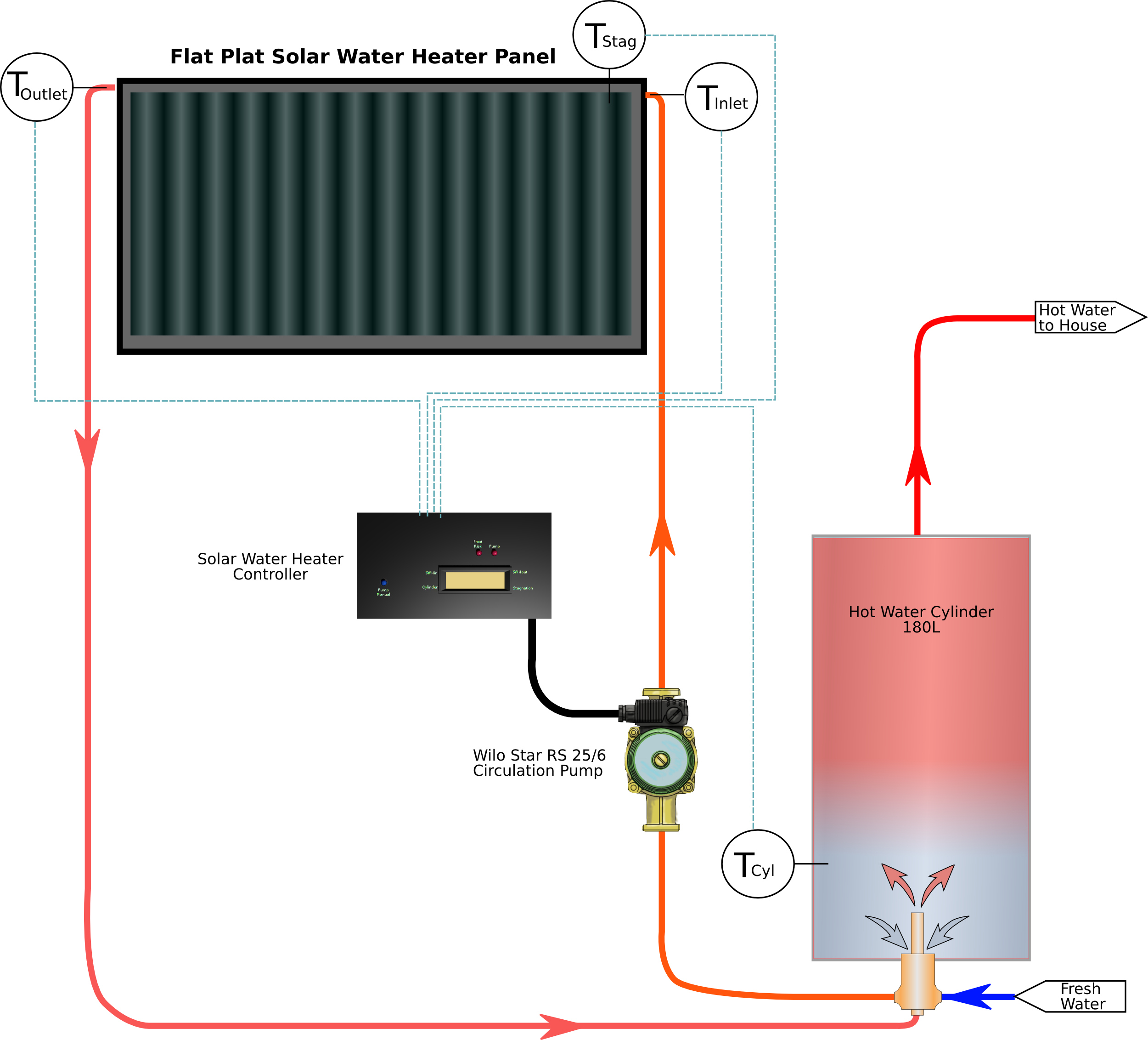
Click on the image for a high resolution version.
This arrangement has excellent positioning of the temperature sensors so they are able to detect the actual heat of the water in the panel. The method that would be required to achieve this would be probes that project into the water pipes as they exit and enter the solar water heater. It also makes use of an ideal location on the hot water storage tank where it can detect the actual water temperature close to where the solar water heater draws from and where cold water enters. Finally the biggest assumption is that the arrangement for the Stagnation Temperature sensor is a true approximation of the solar water heater panel performance.
What’s Stagnation Temperature?
The stagnation temperature for a solar water heater is the temperature the solar water heater will heat to if no water is drawn off. On an overcast day it could be quite close to the ambient temperature. On a sunny day the temperature will be significantly over the ambient temperature because of the absorption of the solar radiation on the black surface of the panel, the insulation on the back side, and the prevention of convective heat loss to the air by having a glass cover.
In this ideal system, the Stagnation Temperature measurement was going to guide the whole system by effectively measuring the quality of the solar radiation. If the stagnation temperature was close to or below the temperature of the cylinder then there was not point in running the pump because there was nothing to be gained. In theory this would have made the system relatively fast to respond to changing cloud cover.
The stagnation temperature sensor also doubled as the frost risk detection temperature sensor. Because the stagnation temperature sensor arrangement has minimal thermal mass compared to the solar water heater panel it would be able to reliably detect when frost conditions were likely without the risk of parts of the panel freezing before the solar water heater inlet or outlet sensors cooled enough to signal the need to go into frost protection mode.
Logic for the Perfect World
The flow diagram presented below is the logic developed to make a responsive system that would react to changes in solar influx quality, temperatures in the hot water storage tank, and on the panels, as well as be able to protect itself from frost damage.
The logic diagram has some hand-waving descriptions of the method used for creating a rolling average to smooth the readings from the sensors.
A debounce process was included to prevent the pump from short cycling when the temperatures were getting close to set points. The period is approximately 8 seconds once a stable signal to start or stop the pump is reached. This is more or less the time it takes for the water to pump through the circuit once.
Reduced wear and tear on both the pump and relay should result from using this approach.
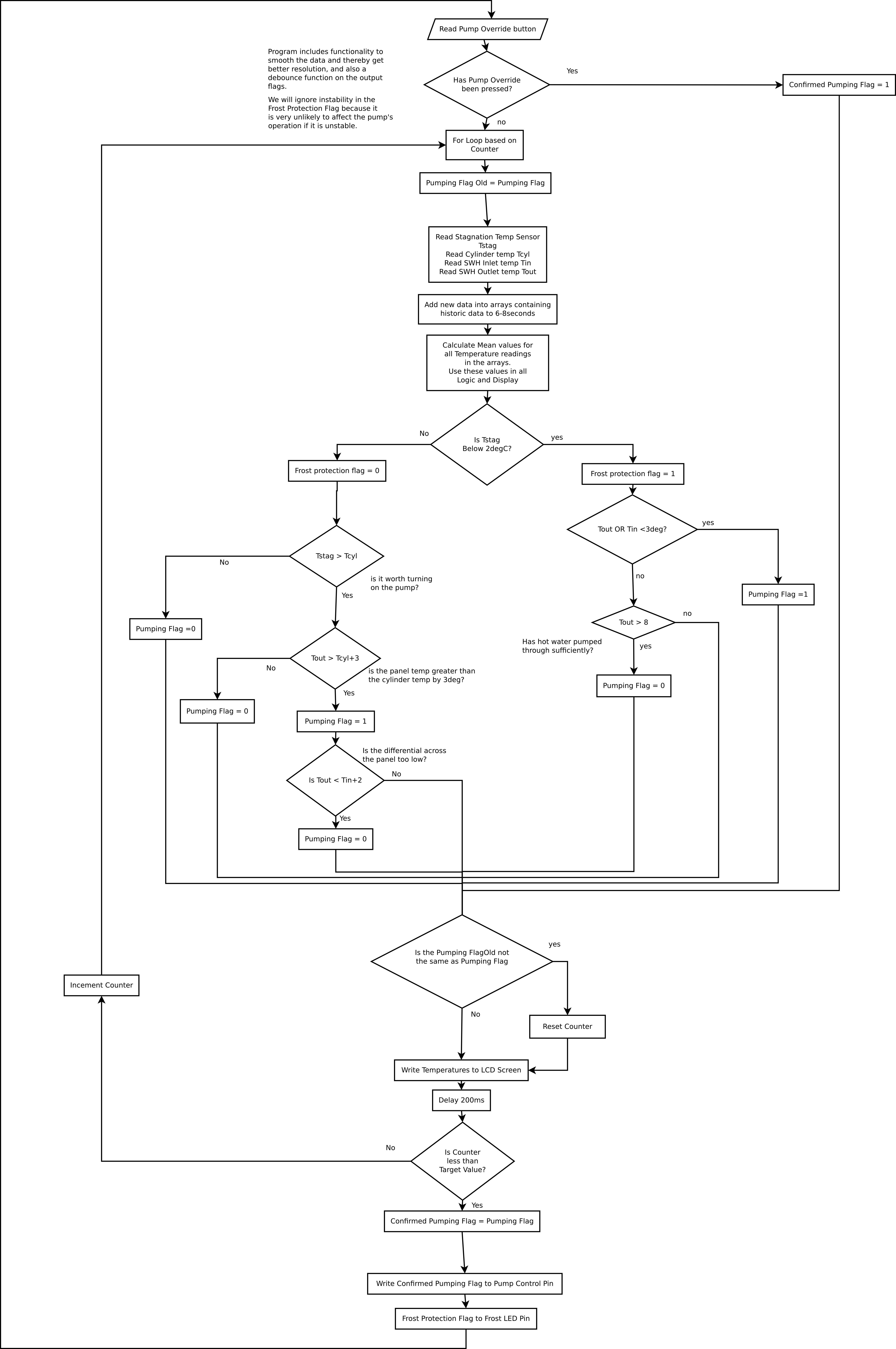
Click on the image for a readable version of this image
Circuit for the Perfect World System
The circuit is relatively simple and was designed to include power from a separate 5V USB power supply if problems with electrical noise interfering with the operation of the Arduino were encountered. It includes a number of extra connections for other buttons should there be a desire to add more functions.
The circuit shown below is the same for both the ideal and real world systems.
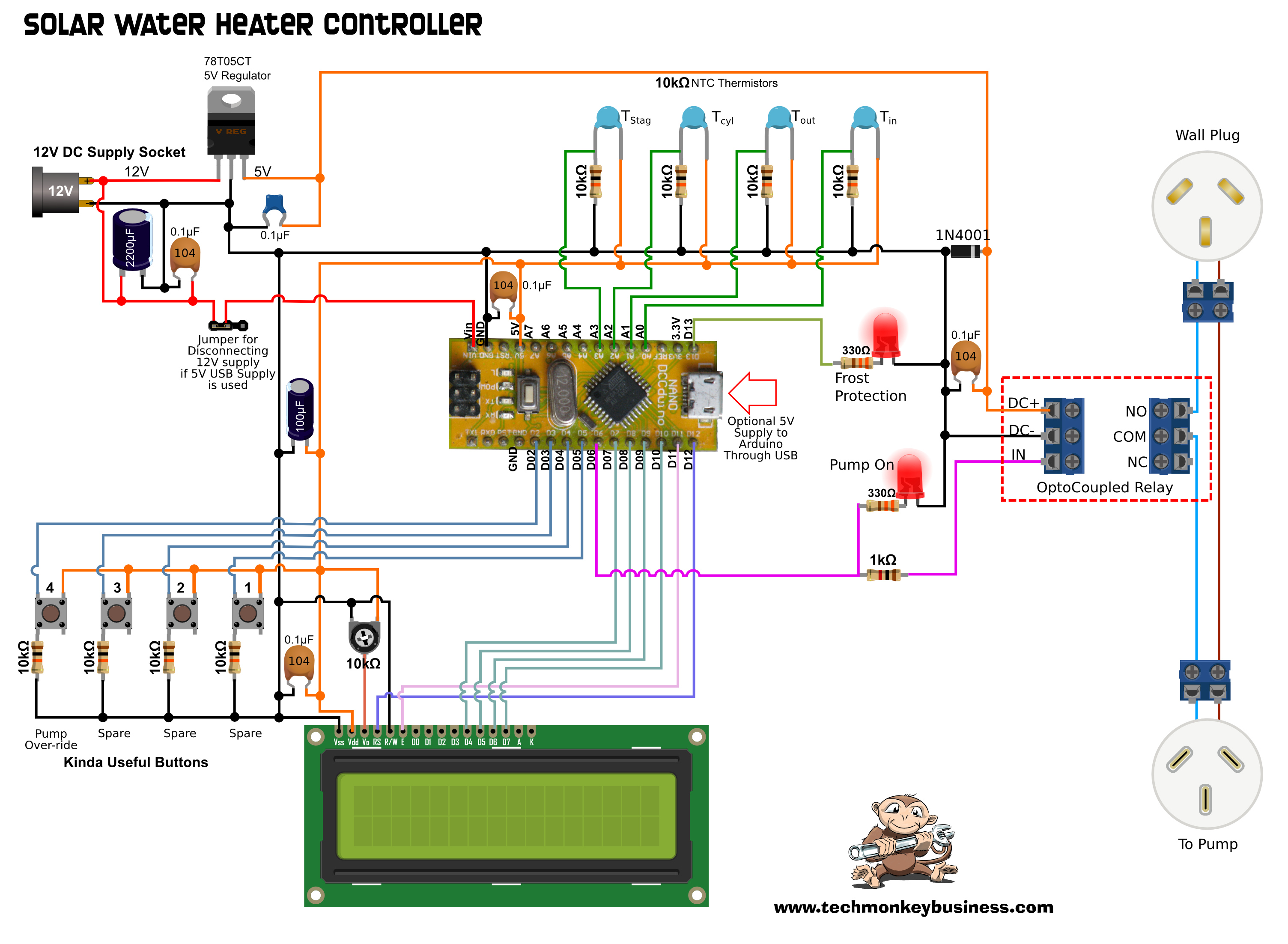
Circuit Diagram - Click on the image for Hi-res version.
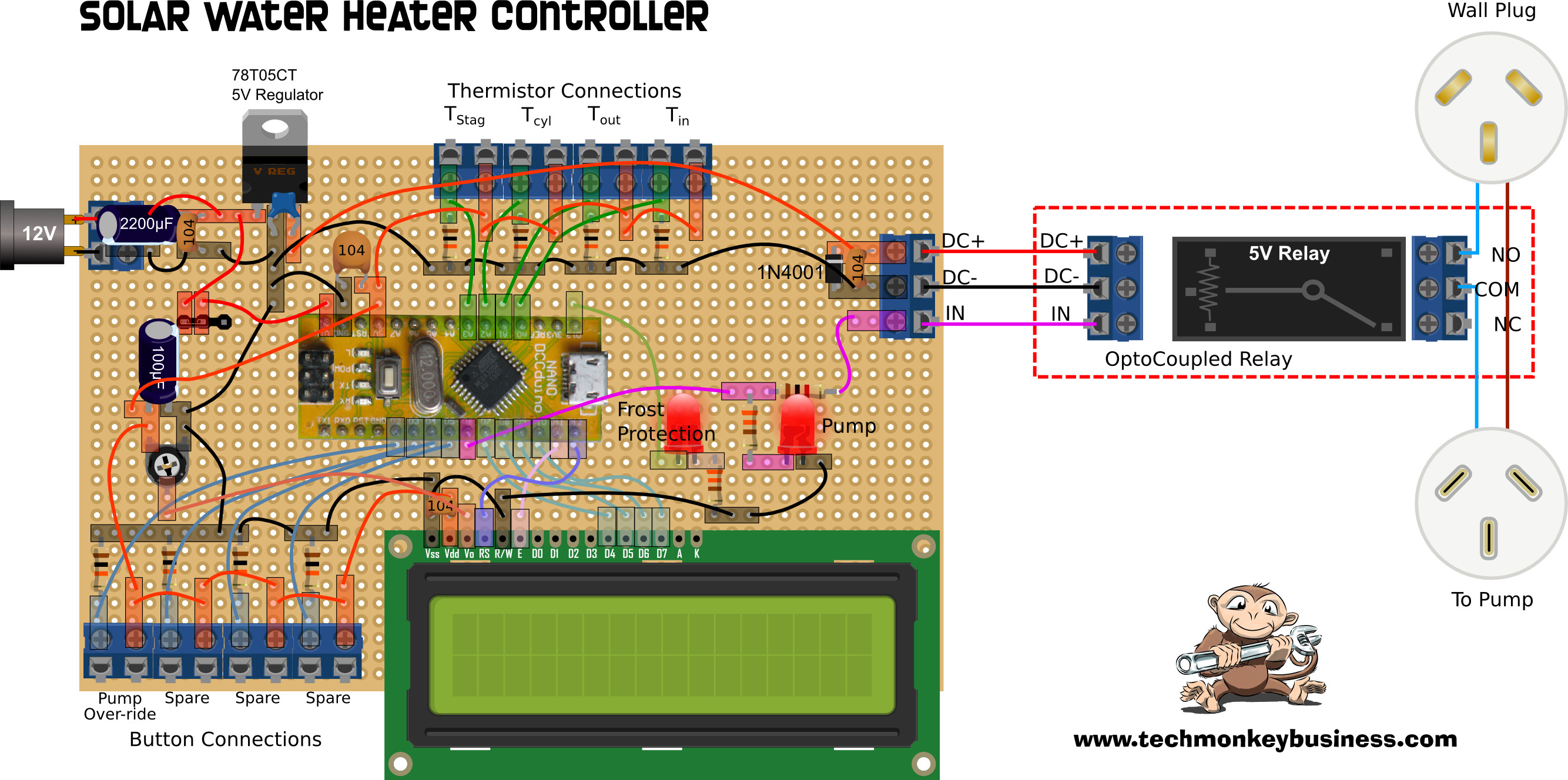
Circuit Board Layout – perf’ board - Click on the image for Hi-res version.
At the heart of the system is an Arduino Nano. The demands on the Arduino are not large and so any Arduino could be used.
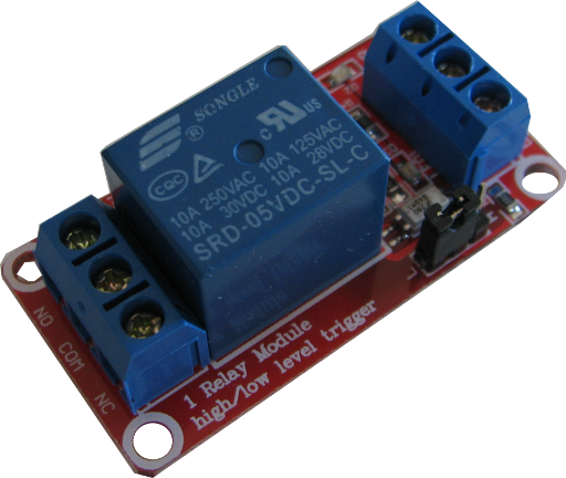
An opto-isolated relay module from Banggood was selected to control the pump. Flyback diodes and various LEDs are included in the package. All it requires is a ground connection, 5v supply, and a signal. Using the jumper on the module the relay can be set to trigger with a high or a low signal. The manufacturer claims the relay can handle 240V 10A AC. I have seen a few comments in various forums that suggest the terminal connections themselves are not capable of carrying that sort of current, but the pump used in our solar water heater system only draws 0.5A anyway, so the module is quite suitable for the task.
The LCD screen is a typical 16x2 type. I have not connected the back light because, why would I want to illuminate the interior of my hot water cupboard. I don’t think the dust mites are into reading at night.
The other components of significance are the thermistors and the 5V regulator.
Here is a list of the components used.
- Arduino Nano.
- LCD display – 16x2. This is not the i2c version – although I would suggest the 12c version might be better.
- Four NTC 10kΩ thermistors with Beta Values of 4100K.
- A button.
- Two LEDs.
- MC78T05CT regulator capable of outputting 3A at 5V not that we’re using anywhere near that much.
- A 2200μF electrolytic capacitor.
- A 100μF capacitor.
- some 10kΩ resistors.
- A couple of 330Ω resistors.
- A 1kΩ resistor.
- A 1N4001 diode acting as a flyback diode for the relay coil, but probably completely superfluous with the flyback diode built into the relay module already.
- A handful of 0.1μF capacitors liberally sprinkled throughout the circuit like “fairydust” as suggested by Adafruit.
Most of the capacitors and the 1N4001 diode were added late in the piece to try to combat the problem with the LCD screen displaying garbage sometimes when the relay opened. They are not necessary for the circuit to work if the power supplied to the Arduino is clean enough. The only capacitor in the pre-real world scheme was the 2200μF electrolytic capacitor on the regulator inlet side.
Coding for the Perfect World System
Here is the code for the perfect world system. You will notice the key role of the stagnation temperature (Tstag) in this. In the real-world version this was set in such a way that it would enable to the pump to run in most conditions even those that would be really dull and miserable. It’s major role was relegated to frost protection.
Hopefully the comments through the sketch will explain how it works.
You can download the sketch from here: SWHControllerv4.ino
The sketch does not use any libraries that don’t come with the standard Arduino IDE. I think it works on older versions of the Arduino IDE too. In short, there is nothing particularly fancy in this coding.
/*
 * SWHControllerv4.ino
 * Hamish Trolove 2017 - www.techmonkeybusiness.com
 *
 * This sketch is to run a solar water heater and optimise the solar heat
 * yield.  It is also designed to be easily modified to suit local conditions.
 * A process similar to the Debounce routine in the Arduino Cookbook (pg155)
 * has been used to protect against short cycling of the pump. In addition to
 * this the Array average process (https://www.arduino.cc/en/tutorial/smoothing)
 * has been used on all data to smooth the temperature readings and gain better
 * resolution.
 *
 * There are four thermistors which are located;
 * Solar Water Heater Inlet - Tin
 * Solar Water Heater Outlet - Tout
 * Tank Skin on the lower part - Tcyl
 * and Tstag on a black plate in a pyrex tube to measure stagnation
 * temperatures and frost conditions.
 *
 * The temperatures will control the operation of a pump through an optically isolated relay.
 *
 * Each thermistor reading is displayed on the 16x2 LCD screen.
 *
 * Four buttons are connected.  At this stage only one is used and that is an override to turn
 * on the pump.
 *
 * Circuit is described on www.techmonkeybusiness.com.
 *
 * Connections are:
 *
 * 10K B=4100 NTC Thermistors with 10K resistors in voltage dividers on A0, A1, A2, and A3
 * Push buttons with pull up resistors on D02, D03, D04, and D05
 * LED to indicate Frost Protection mode on D13
 * Pump relay control line on D06 (also connected to an LED)
 * LCD connections:
 * D12 to LCD RS pin
 * D11 to LCD E pin
 * D10 to LCD D7 pin
 * D09 to LCD D6 pin
 * D08 to LCD D5 pin
 * D07 to LCD D4 pin
 *
 *The LCD panel is not lit.
 */

#include <LiquidCrystal.h>
#include <math.h>  // We need this to calculate temperature values from thermistors.
const int ThermPinA = A0;  // The Tin thermistor on Analogue Pin 0
const int ThermPinB = A1;  // The Tout thermistor on Analogue Pin 1
const int ThermPinC = A2;  // The Tcyl thermistor on Analogue Pin 2
const int ThermPinD = A3;  // The Tstag thermistor on Analogue Pin 3

const int ButtonA = 02; // Some button pins defined (Pump Override)
const int ButtonB = 03;
const int ButtonC = 04;
const int ButtonD = 05;

const int LEDFrost = 13; // Front protection mode indicator LED
const int LEDPump = 6; // Pump running indicator LED.

boolean PumpFlag = false; //This is the flag to control the pump.  All
                          //control logic acts on this flag.
boolean FrostRisk = false; //Frost risk flag for driving LED.
boolean PumpFlagOld = false; //Flag to hold previous PumpFlag State
boolean ConfirmPumpRun = false; //Once all debouncing has occurred this is
                                //the flag to run the pump.

int CycleCount = 0;  //A counter for the number of times the loop has run for
                     //while awaiting stable readings.
int ThermValue = 0; // Somewhere to stick the raw Analogue Pin Value.
double Tin = 0.00; // Calculated Temperature Values after smoothing
double Tout = 0.00;
double Tcyl = 0.00;
double Tstag = 0.00;

//Arrays to hold historic data
const int numReadings = 40;

double TinArray[numReadings];      // the readings from the Temperature sensors
double ToutArray[numReadings];
double TcylArray[numReadings];
double TstagArray[numReadings];

double Tintotal = 800;   // the running totals for the temperature readings
double Touttotal = 800;  //Starting value is 20 x 40 ie starting value
double Tcyltotal = 800;  //in arrays.  If the arrays had been loaded with
double Tstagtotal = 800; //zeros then these figures would also be zero.

int readIndex = 0;              // the index of the Historic Data Array Pointer

double FrostTemp = 2.00; //Temperature below which Frost is a risk.
                      //Adjust for local conditions.
double SWHFrostThresh = 3.00; //Temperature at SWH at which pump
                      //will start if running in Frost protection mode.
double SWHOutHeatedTemp = 8.00; //Temperature which will indicate that
                      //hot water is in SWH for frost protection.
double SWHCylTdiff = 3.00; //Temperature difference between cylinder
                      //and solar water heater before pumping starts.
double SWHTdiff = 2.00;  //Min temperature difference across the solar
                      //heater before pumping is stopped.

LiquidCrystal lcd( 12, 11, 7, 8, 9, 10 );   //Pins for the LCD Screen


void setup()
{
  lcd.begin(16, 2);  //set up the LCD's number of columns and rows:
  lcd.setCursor(0, 0);
  lcd.print("Starting");  //Print a message to the LCD
  pinMode(ThermPinA, INPUT);
  pinMode(ThermPinB, INPUT);
  pinMode(ThermPinC, INPUT);
  pinMode(ThermPinD, INPUT);
  pinMode(ButtonA, INPUT);  //This is the pump override button.
  pinMode(ButtonB, INPUT);  //spare
  pinMode(ButtonC, INPUT);  //spare
  pinMode(ButtonD, INPUT);  //spare
  pinMode(LEDFrost, OUTPUT);
  pinMode(LEDPump, OUTPUT);

  //Load the arrays with normal(ish) values to begin with.
  for (int Indexer = 0; Indexer < numReadings; Indexer++)
  {
    TinArray[Indexer] = 20.00;
    ToutArray[Indexer] = 20.00;
    TcylArray[Indexer] = 20.00;
    TstagArray[Indexer] = 20.00;
  }
  delay(2000);
}

void loop()
{
  //Look to see if the pump override button pressed.
  if(digitalRead(ButtonA)==HIGH)
  {
    ConfirmPumpRun = true;
  }
  else  //if pump override button not pressed then all is running automatically.
  {
    //The debounce process looks to see if the PumpFlag has remained stable for
    //eight seconds or to a count of about 40 ... more or less.

    for(CycleCount = 0; CycleCount < 40; CycleCount++)
    {
      PumpFlagOld = PumpFlag;


      //The next few bits are the smoothing process.
      //Remove the reading being replaced from the running total.
      Tintotal =  Tintotal - TinArray[readIndex];    // the running totals for
      Touttotal = Touttotal - ToutArray[readIndex];   //the temperature readings
      Tcyltotal = Tcyltotal - TcylArray[readIndex];
      Tstagtotal = Tstagtotal - TstagArray[readIndex];


      //Read the Thermistor Data into the arrays
      ThermValue = analogRead(ThermPinA);  //What is the raw value from the Voltage Divider?
      TinArray[readIndex] = TempCalc(ThermValue);  //Just duck out to the calculation routine.
      ThermValue = analogRead(ThermPinB);
      ToutArray[readIndex] = TempCalc(ThermValue);
      ThermValue = analogRead(ThermPinC);
      TcylArray[readIndex] = TempCalc(ThermValue);
      ThermValue = analogRead(ThermPinD);
      TstagArray[readIndex] = TempCalc(ThermValue);

      //Add the new readings to the total
      Tintotal =  Tintotal + TinArray[readIndex];    //This process has swapped an old
      Touttotal = Touttotal + ToutArray[readIndex];  //value for a new one and updated the
      Tcyltotal = Tcyltotal + TcylArray[readIndex];  //total.  It is efficient with regard
      Tstagtotal = Tstagtotal + TstagArray[readIndex]; //to minimised double handling.

      //move the pointer along a bit.
      readIndex = readIndex + 1;
      //check to see if we've exceeded the array positions
      if (readIndex >= numReadings)
      {
        readIndex = 0;  //reset the pointer position to start of arrays.
      }

      //Calculate the 8 second average for use in the control logic to follow.
      Tin = Tintotal / numReadings; // Calculated Mean Temperature Values
      Tout = Touttotal / numReadings;
      Tcyl = Tcyltotal / numReadings;
      Tstag = Tstagtotal / numReadings;


      //Check whether there is a frost risk.
      if(Tstag < FrostTemp)
      {
        //Frost risk conditions are present.
        FrostRisk = true;
        //Has the solar water heater cooled to SWHFrostThresh temperature?
        if( Tout < SWHFrostThresh || Tin < SWHFrostThresh)
        {
          PumpFlag = true;  //If either SWH sensors are cold, turn on the pump
        }
        else
        {
          //The panel is still a little warm
          if(Tout > SWHOutHeatedTemp)
          {
            //The SWH has now got a fresh shot of hot water in it so the
            //pump can be turned off.
            PumpFlag = false;
          }
        }
      }
      else //The conditions are not at risk of freezing
      {
        FrostRisk = false;
        //Check to see if the stagnation temperature is greater than the
        //hot water cylinder temperature.  If it is then it may be worth
        //running the pump.  If it's not then it's probably a fairly dull day.
        if(Tstag > Tcyl)
        {
          //It is a moderately sunny day and there is heat to be gained.

          //Is the SWH outlet temperature greated than the Tank cylinder temp
          //plus the threshhold value SWHCylTdiff.
          if(Tout > Tcyl + SWHCylTdiff)
          {
            //The SWH is hotter than cylinder by an appropriate margin so
            //start the pump.
            PumpFlag = true;
            if(Tout < Tin + SWHTdiff)
            {
              //The temperature difference across the panel is too low.  The quality of solar
              //intensity is too low.  Turn off the pump.
              PumpFlag = false;
            }
          }
          else
          {
            //The temperature differential between panel and cylinder to too low.
            PumpFlag = false;
          }
        }
        else
        {
          //There's no point running pump on a dull day.
          PumpFlag = false;
        }
      }
      //Checking the stability of the Pump state for both normal and frost operation.

      if(PumpFlagOld != PumpFlag)
      {
        CycleCount = 0;  //Unstable conditions therefore reset the counter.
      }

      // Display the readings on the LCD Display
      lcd.clear();
      lcd.setCursor(0, 0);
      lcd.print(Tin);
      lcd.setCursor(7, 0);
      lcd.print(Tout);
      lcd.setCursor(0, 1);
      lcd.print(Tcyl);
      lcd.setCursor(7, 1);
      lcd.print(Tstag);
      delay(200);

    }


    ConfirmPumpRun = PumpFlag;  //At last a status is decided for normal operation.
  }


  digitalWrite(LEDPump, ConfirmPumpRun); //This makes the pump run and lights pump LED.
  digitalWrite(LEDFrost,FrostRisk);


}


double TempCalc(int ThermIn)
{
  double TempVal = 1/((1/298.00)+(1/4100.00)*log(1024.00/ThermIn-1.00));
  TempVal = TempVal - 273.00;  //Note the extra decimal places force float usage.
  return TempVal;
}
Page Updated 22 March 2017
The information provides is accurate to the best of my knowledge, but describes what I did and what worked for me. No responsibility is accepted for any failure of equipment or damage caused by attempting to follow these instructions. You’re probably working with main electricity, so watch what you’re doing with that stuff. It bits hard. The information is also provided in an as-is-where-is basis and as such I cannot provide support to help you solve your own problems you may encounter.