Multi-Joysticks transmitted to Multiple Servos
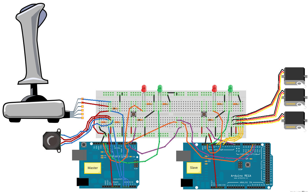
In order to send complex control commands to a remote device more complex messages are required. This development sketch reads the positions of three joysticks (potentiometers) packages the data as a comma separated variable message to the remote slave Arduino for translation into commands for the servos or ESCs that the ROV would have.
In this case we have used the old PC Raider joystick and a single thumb joystick. The PC raider Y-axis seems a bit flaky it it was not used. The thumb-joysticks have a resistance range of 1.6kohms to 4.8kohms with the neutral position being 3.2kohms. All joystick analogue pins were pins A0, A1, and A2 on the Arduino UNO and the MEGA used PWM pins D7, D8, and D9 for controlling the servos. As an update to this, PS2 controllers will be used as the complete control interfaces for this project because they are robust, have enough controls, and are readily available new at an excellent price.
There is still a need for scaling of the variables at the Master end to suit the resistances in use.
See also:
Communication between Arduinos - I2C and Communication between Arduinos - Serial.
A higher resolution image can be found here
The Master and Slave sketches can be downloaded from here: Serial_MultiJoystick_Masterv0_and_Slavev0.zip
Master Sketch
/* Serial_MultiJoystick_Masterv0
This sketch is one of two for sending information between two
Arduinos using serial communication to achieve communication down
a long wire.
This sketch is the master and will read a single channel from
a PC Raider Joystick (Potentiometers)on analogue pin 0, two axis from a
thumbjoystick (analogue pins A1 and A2) then send the data to a
slave Arduino via the Serial Port (Digital pins 0 and 1).  The format
for the data will be as a three component CSV.
The slave Arduino will take that information and use it to move a
series of three servos.

This sketch also includes an interrupt button to enable and disable
sketch.  This is included so that the sketch can be stopped to allow
new uploads seeing as it is using Serial and I2C communication that
would otherwise block this process.  LEDs are used to indicate the
enabled or disabled state.

This sketch is based on Serial_Joystick_Masterv1 which works over the
100m OpenROV tether.
*/

#include <SoftwareSerial.h>

const int rxpin = 3;  // New Soft Serial receive pin on UNO
const int txpin = 4;  // New Soft Serial Transmit pin on UNO
SoftwareSerial serial_ard(rxpin, txpin);  //Set up the extra Serial Port
const int PCRjoypin = 0; // analog pin used to connect the PC Raider Joystick axis
const int ThbJoyXpin = 1;  // analogue pin to connect the X-axis of the Thumbjoystick
const int ThbJoyYpin = 2;  // analogue pin to connect the Y-axis of the Thumbjoystick
int PCRval;  // variable to read the value from the PC Raider analog pin
int TMJXval;  // variable to read the value from the Thumb Joystick X-axis analog pin
int TMJYval;  // variable to read the value from the Thumb Joystick Y-axis analog pin
const int grnLEDpin = 12;  //green LED is on Digital pin 12
const int redLEDpin = 13;  //red LED is on Digital pin 13.
const int Button = 2;  //Button is on Digital pin 2
volatile boolean Toggle;    //Introduce the controlling switch.
  //which will change with the interrupt.

void setup()
{
  Serial.begin(9600);  //Port for communication to computer for debugging
  serial_ard.begin(9600);  //Baud 9600 is good for 300m lines.
  pinMode(grnLEDpin, OUTPUT);  //Sets the grnLEDpin to output
  pinMode(redLEDpin, OUTPUT);  //Sets the grnLEDpin to output
  pinMode(Button,INPUT);  //Sets the Button to input.
  Toggle = false;  //Sets the condition toggle
  attachInterrupt(0,FFlag,FALLING);  //Sets up the Interruptor
    //on pin 2,and calls subroutine FFlag when the button value falls.
   //using FALLING helps avoid the blink jittering if the button is held.
}

void loop()
{
  if(Toggle == false)
  {
    digitalWrite(redLEDpin,HIGH); // indicate system disabled by using red LED
    digitalWrite(grnLEDpin,LOW);  // indicate system disabled by turning off green LED
  }
  else
  {
    digitalWrite(redLEDpin,LOW); // indicate system enabled by turning off red LED
    digitalWrite(grnLEDpin,HIGH);  // indicate system enabled by lighting green LED
    DoStuff();  //Execute the DoStuff subroutine.
  }
  delay(15);  // 15 millisecond delay
}

void DoStuff()
{
  // Read the PC Raider Joystick
  PCRval = analogRead(PCRjoypin);// reads the value of the joystick (value between 0 and 1023)
  PCRval = map(PCRval, 415, 1023, 0, 179);
  // scale it to use it with the servo (value between 0 and 180)

  // Read the X-axis of the thumb Joystick
  TMJXval = analogRead(ThbJoyXpin);// reads the value of the joystick (value between 0 and 1023)
  TMJXval = map(TMJXval, 200, 800, 0, 179);
  // scale it to use it with the servo (value between 0 and 180)

  // Read the Y-axis of the thumb Joystick
  TMJYval = analogRead(ThbJoyYpin);// reads the value of the joystick (value between 0 and 1023)
  TMJYval = map(TMJYval, 200, 800, 0, 179);
  // scale it to use it with the servo (value between 0 and 180)

  //Put it all together into a CSV message through the Soft Serial port

  // Send the message to the USB serial port for the Port Monitor
  Serial.print(PCRval); // Send the PC Raider value to the Monitor
  Serial.print(",");
  Serial.print(TMJXval);  //Send the Thumbjoystick X-axis value value to the Slave Arduino
  Serial.print(",");
  Serial.print(TMJYval);  //Send the Thumbjoystick Y-axis value value to the Slave Arduino
  Serial.print(",");  // final comma to aid message end detection
  Serial.println();  // finish the message with a cr/lf.

  // Sending the message to the other Arduino via the Soft Serial line
  serial_ard.print(PCRval);  //Send the PC Raider sensor value to the Slave Arduino
  serial_ard.print(",");
  serial_ard.print(TMJXval);  //Send the Thumbjoystick X-axis value value to the Slave Arduino
  serial_ard.print(",");
  serial_ard.print(TMJYval);  //Send the Thumbjoystick Y-axis value value to the Slave Arduino
  serial_ard.print(",");  // final comma to aid message end detection
  serial_ard.println();  // finish the message with a cr/lf.
}

void FFlag()
{
  Toggle = !Toggle; //The should switch the value - "!" means NOT
}
Slave Sketch
/* Serial_MultiServo_Slavev0
This sketch is one of two for sending information between two
Arduinos.  This one is the slave and will take the series of values
corresponding to the positions of a PC Raider Joystick and a Thumb Joystick
which has been sent via the Serial communication.  The values are
used to move a series of three servos.

This development sketch needs an Arduino Mega so that the commands
from the Master can be received into an alternative Serial Port
and still be able to report to the computer through the regular
Serial Port.  If another UNO were to be used or a Seeeduino Stalker
and software serial port would need to be created to receive the
messaged from the Master.

This sketch also includes an interrupt button to enable and disable
sketch.  This is included so that the sketch can be stopped to allow
new uploads seeing as it is using Serial and I2C communication that
would otherwsie block this process.  LEDs are used to indicate the
enabled or disabled state.

Based on Serial_Slavev2
*/
#include <Servo.h>
Servo PCRservo; // create servo object to control a servo corresponding to the PCR Raider Joystick
Servo TMJXservo; // create servo object to control a servo corresponding to the ThumbJoystick X-axis
Servo TMJYservo; // create servo object to control a servo corresponding to the ThumbJoystick Y-axis
const int NoF = 3;  //Number of fields expected in message - increase as more sensors added
int val[NoF];      //declare an array to hold the transmitted data
const int grnLEDpin = 12;  //green LED is on Digital pin 12
const int redLEDpin = 13;  //red LED is on Digital pin 13.
const int Button = 2;  //Button is on Digital pin 2
int fieldIndex = 0;  //Pointer for the array contents
volatile boolean Toggle;    //Introduce the controlling switch.
  //which will change with the interrupt.

void setup()
{
  pinMode(grnLEDpin, OUTPUT);  //Sets the grnLEDpin to output
  pinMode(redLEDpin, OUTPUT);  //Sets the grnLEDpin to output
  pinMode(Button,INPUT);  //Sets the Button to input.
  Toggle = false;  //Sets the condition toggle
  Serial.begin(9600);  //Serial port for computer communications
  Serial1.begin(9600);  //Serial port for Master communications
  PCRservo.attach(9);// attaches the PC Raider associated servo on pin 9 to the servo object
  TMJXservo.attach(8);// attaches the thumbjoy X-axis associated servo on pin 8 to the servo object
  TMJYservo.attach(7);// attaches the thumbjoy Y-axis associated servo on pin 7 to the servo object
  attachInterrupt(0,FFlag,FALLING);  //Sets up the Interruptor
    //on pin 2,and calls subroutine FFlag when the button value falls.
   //using FALLING helps avoid the blink jittering if the button is held.
  val[0] = val[1] = val[2] = 90;  // default positions array
}

void loop()
{
  if(Toggle == false)
  {
    digitalWrite(redLEDpin,HIGH); // indicate system disabled by using red LED
    digitalWrite(grnLEDpin,LOW);  // indicate system disabled by turning off green LED
  }
  else
  {
    digitalWrite(redLEDpin,LOW); // indicate system enabled by turning off red LED
    digitalWrite(grnLEDpin,HIGH);  // indicate system enabled by lighting green LED
    DoStuff();  //Execute the DoStuff subroutine.
    PCRservo.write(val[0]); // sets the PC Raider Associated servo according to the scaled value received through the Serial
    TMJXservo.write(val[1]); // sets the Thumbjoy X-axis Associated servo according to the scaled value received through the Serial
    TMJYservo.write(val[2]); // sets the Thumbjoy Y-axis Associated servo according to the scaled value received through the Serial
  }
  delay(15);  // 15 millisecond delay
}

void DoStuff()  //how many degrees for the servo
{
  if(Serial1.available()) //while there is data available
  {
    for(fieldIndex = 0; fieldIndex < 3; fieldIndex ++)
    {
      val[fieldIndex]=Serial1.parseInt();  //pull out the numerical bit
    }
    for(int i=0;i<3;i++)
    {
      Serial.print(val[fieldIndex]);  //report on what is happening
      Serial.print(" ");
    }
    Serial.println();
    fieldIndex = 0; //reset the pointer for the next message.
  }
}

void FFlag()
{
  Toggle = !Toggle; //The should switch the value - "!" means NOT
}