Steely Taws Components
This is a description of the components used in the “Steely Taws” puzzle game. Hopefully this will give you an idea of how to make use of them should you wish to use them in your own games and puzzles. In most cased clicking on the images below will open a hi-resolution version which will be more readable.
The components can be downloaded using this link: Steely Taws Component Models
Some of the components have been reissued with standardised dimensions and origin point locations to allow for easier building of networks and layouts. These are described on this page: Standardised Steely Taws Components. The use of these standardised components and the Blender plugin Sverchok to produce automatically generated levels is demonstrated by my partner Elfnor on her website; Elfnor’s Blender Game Level Generator and in the Third edition of the Steely Taws game which can be found here: Version 3 of the Steely Taws game.
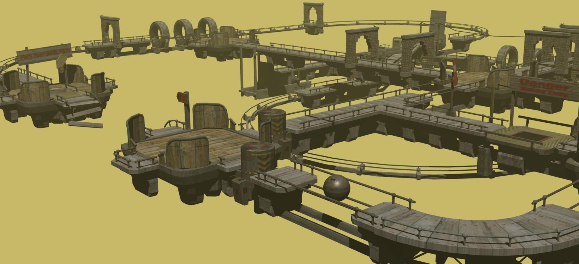
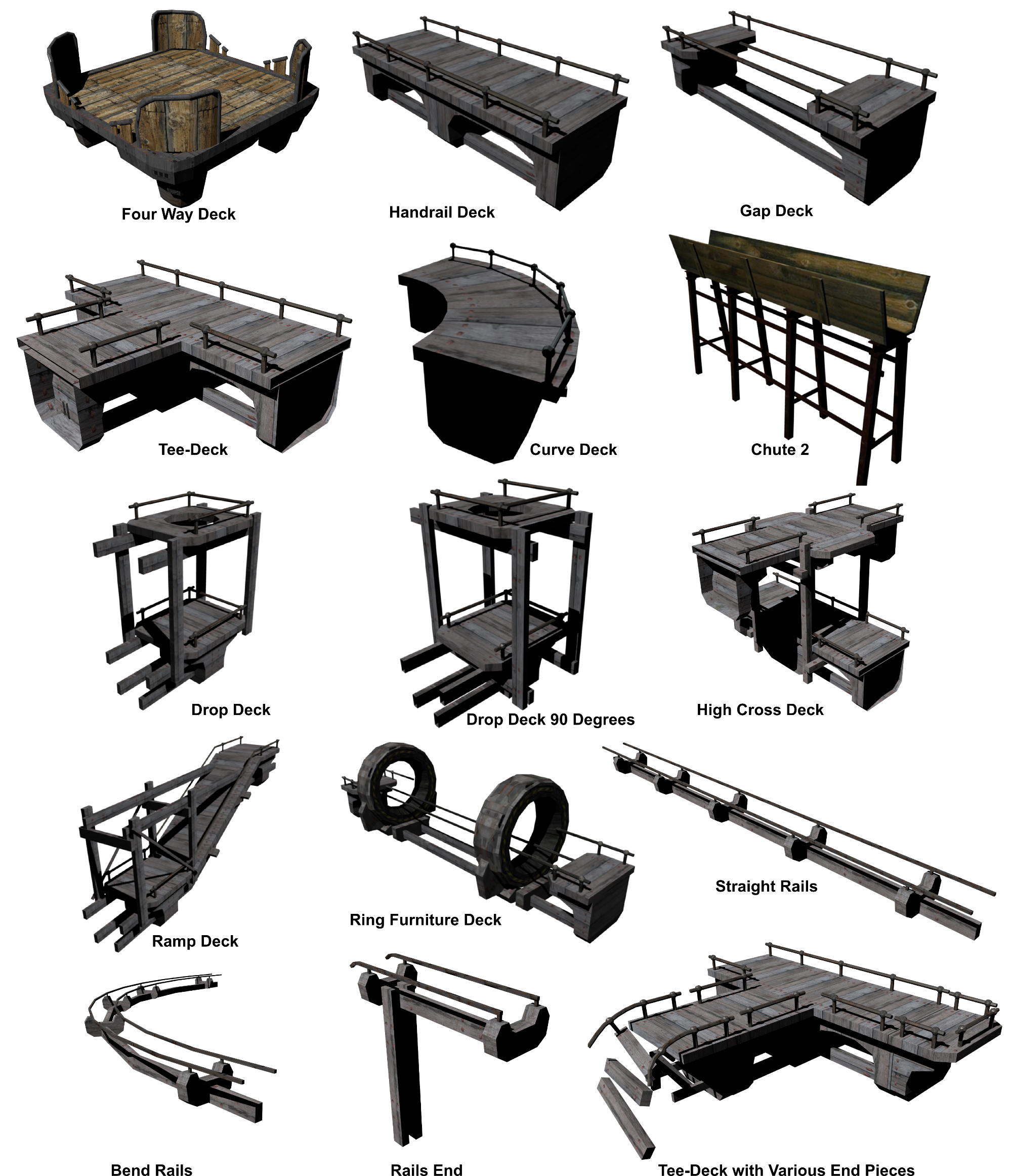
Static Elements
There are a number of static elements of one sort or another which make up the majority of the geometry in the game levels. These are various types of straight pieces, curves, drop downs, decks, ramps, and blank ends. Parallel rails are also used here to add interest as well as dissuade the player from trying to take other objects along those routes.
All of these components are introduced into the levels as Static Meshes (Physics Type: Static) and use their actual mesh for collisions. This gives a good level of realism to the interaction between the ball and the scenery geometry.
Here is the gallery of static components (Click on the image for a larger view).
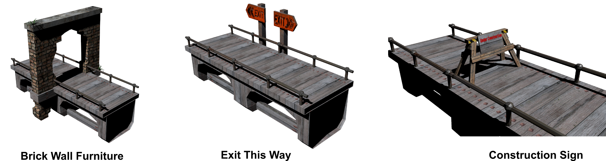
There are several decorative or “informative” static components too which are designed to add interest to the scene or obstruct the view as the case may be.
Active Elements
The active elements have some degree of interactivity to them and typically carry logic blocks. Some refer to python code as well. This code is provided in the descriptions below.
In a number of cases animations are used to control the motion. If you are planning to use these components, I would suggest stripping off any animation before you move the component to the final position and then rebuild the animation. The reason for this is that I was unable to get relative positions for the animations to happen and so had to rely on absolute positions.
Taws-Core-v0.blend
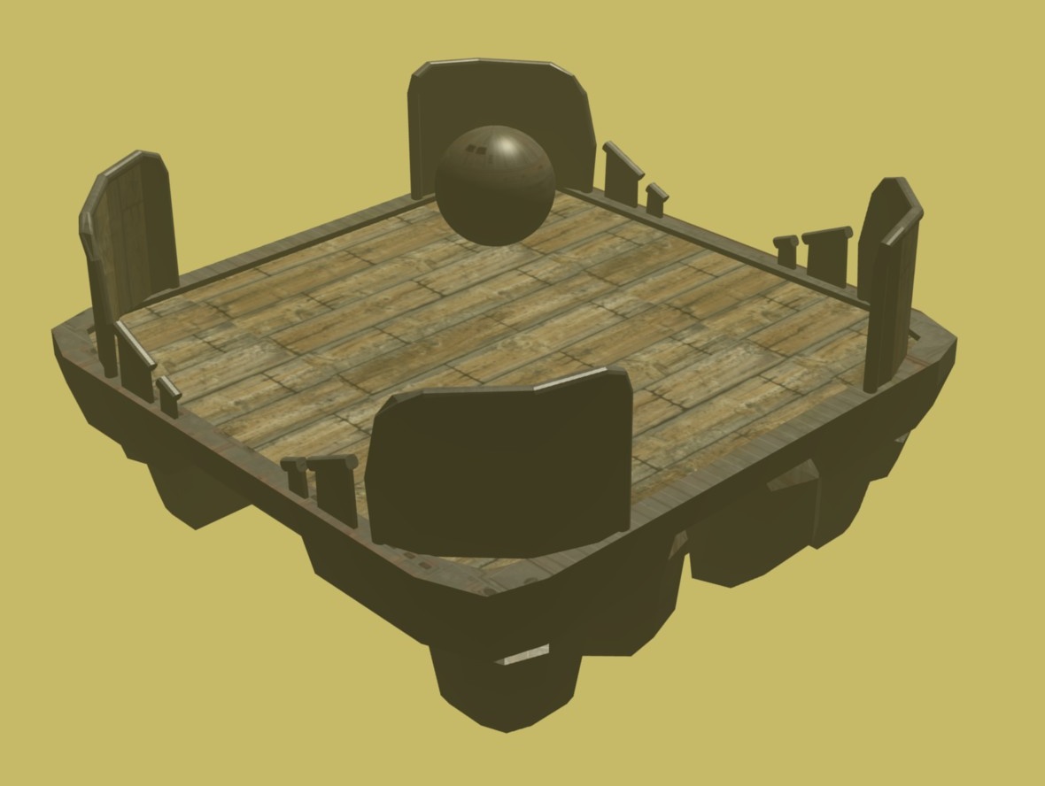
This is the basic component of a level. It consists of the ball with all of its coding, the camera, and the plane that sits underneath the game level to catch any falling objects. The scene also includes a sun object and a four way deck for the ball to sit on.
If you need to reposition the ball to a new starting location you will need to update the python script associated with the Reset Plane to return the ball to the new position you have chosen.
The functionality of the ball has been described in detail in the first edition “Steely Taws – No Quitsies” webpage but has been repeated here for completeness.
The Ball
The focus of the game is the ball and moving it about the environment using the keyboard controls or the joystick. Here is the overview of the logic blocks for the ball. The logic blocks are relatively straight forward and accept user input through the keyboard or joystick sensors, and when the ball is in contact with something forces will be applied to the ball to move it. The forces are applied in a view relative manner to make control of the ball feel more natural for the player. A python script called ViewForce.py is required to apply these forces in such a manner.
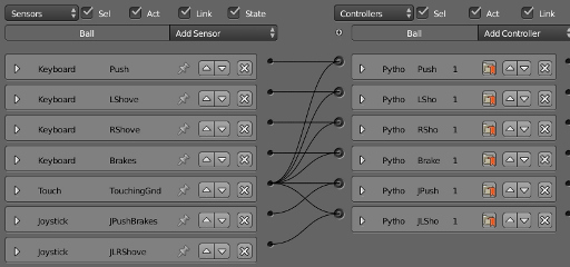
Ball Logic blocks collapsed view for simplicity
Below is the expanded version of the above series of logic controls. As you will see, all of them except the Touch sensor provide pulses.
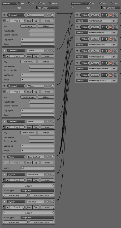
On the right hand side are the Python controllers. These all call on modules within the Viewforce.py script based on the key pressed or joystick axis used. The modules are:
ViewForce.Pushto apply a force away from the viewViewForce.LShoveto apply a force to drive the ball to the left side of the viewViewForce.RShoveto apply a force to drive the ball to the right side of the viewViewForce.Brakesto apply a force towards the viewer.ViewForce.JPushBrakesto apply a force toward or away from the viewer when the joystick is pushed forward or backward.ViewForce.JLRShoveto apply a force to either side of the ball when the joystick is pushed left or right.
The python code for ViewForce.py:
import bge
import mathutils
import math


cont = bge.logic.getCurrentController()
own = cont.owner

#A 90 degree transform matrix about Z looks like
#[0 1 0],[-1,0,0][0,0,1]
mat_rot = mathutils.Matrix(((0,1,0),(-1,0,0),(0,0,1)))


def Push(cont):

    sens = cont.sensors['Push']
    Contact1=cont.sensors['TouchingGnd']

    if sens.positive and Contact1.positive:
        Ball2Cam = own.getVectTo('Camera')
        #print(Ball2Cam)
        Ball2CamVecN=Ball2Cam[1] #pull out the world Vector component
        Ball2CamVecN2D=Ball2CamVecN.to_2d() # This cuts the vector down to just x and y

        #Normalise the vector back to a Unit vector
        Ball2CamVecN2D= Ball2CamVecN2D.normalized()

        #Add 0 into the z direction part of the vector

        Ball2CamVecN3D=Ball2CamVecN2D.to_3d()
        #print(Ball2CamVecN)
        BallForce = -10*Ball2CamVecN3D
        own.applyForce(BallForce,False)
        #print(BallForce)


def LShove(cont):

    sens = cont.sensors['LShove']
    Contact1=cont.sensors['TouchingGnd']

    if sens.positive and Contact1.positive:
        Ball2Cam = own.getVectTo('Camera')
        #print(Ball2Cam)
        Ball2CamVecN=Ball2Cam[1] #pull out the world Vector component
        Ball2CamVecN2D=Ball2CamVecN.to_2d() # This cuts the vector down to just x and y

        #Normalise the vector back to a Unit vector
        Ball2CamVecN2D= Ball2CamVecN2D.normalized()

        #Add 0 into the z direction part of the vector

        Ball2CamVecN3D=Ball2CamVecN2D.to_3d()


        #print(Ball2CamVecN3D)

        #Now make the vector perpendicular
        # around the Z axis, is a 90 degree rotation.

        Ball2CamVecN3D=Ball2CamVecN3D*mat_rot

        BallForce = -10*Ball2CamVecN3D
        own.applyForce(BallForce,False)


def RShove(cont):

    sens = cont.sensors['RShove']

    Contact1=cont.sensors['TouchingGnd']

    if sens.positive and Contact1.positive:
        Ball2Cam = own.getVectTo('Camera')
        #print(Ball2Cam)
        Ball2CamVecN=Ball2Cam[1] #pull out the world Vector component
        Ball2CamVecN2D=Ball2CamVecN.to_2d() # This cuts the vector down to just x and y

        #Normalise the vector back to a Unit vector
        Ball2CamVecN2D= Ball2CamVecN2D.normalized()

        #Add 0 into the z direction part of the vector

        Ball2CamVecN3D=Ball2CamVecN2D.to_3d()


        #print(Ball2CamVecN3D)

        #Now make the vector perpendicular
        # around the Z axis, is a 90 degree rotation.

        Ball2CamVecN3D=Ball2CamVecN3D*mat_rot

        BallForce = 10*Ball2CamVecN3D
        own.applyForce(BallForce,False)


def Brakes(cont):

    sens = cont.sensors['Brakes']

    Contact1=cont.sensors['TouchingGnd']

    if sens.positive and Contact1.positive:
        Ball2Cam = own.getVectTo('Camera')
        #print(Ball2Cam)
        Ball2CamVecN=Ball2Cam[1] #pull out the world Vector component
        Ball2CamVecN2D=Ball2CamVecN.to_2d() # This cuts the vector down to just x and y

        #Normalise the vector back to a Unit vector
        Ball2CamVecN2D= Ball2CamVecN2D.normalized()

        #Add 0 into the z direction part of the vector

        Ball2CamVecN3D=Ball2CamVecN2D.to_3d()
        #print(Ball2CamVecN)
        BallForce = 10*Ball2CamVecN3D
        own.applyForce(BallForce,False)

def JPushBrakes(cont):

    sens = cont.sensors['JPushBrakes']
    Contact1=cont.sensors['TouchingGnd']

    if sens.positive and Contact1.positive:
        Ball2Cam = own.getVectTo('Camera')
        #print(Ball2Cam)
        Ball2CamVecN=Ball2Cam[1] #pull out the world Vector component
        Ball2CamVecN2D=Ball2CamVecN.to_2d() # This cuts the vector down to just x and y

        #Normalise the vector back to a Unit vector
        Ball2CamVecN2D= Ball2CamVecN2D.normalized()

        #Add 0 into the z direction part of the vector

        Ball2CamVecN3D=Ball2CamVecN2D.to_3d()
        #print(Ball2CamVecN)
        PushpullF=sens.axisSingle/4000 #Read the Joystick sensor
        BallForce = PushpullF*Ball2CamVecN3D
        own.applyForce(BallForce,False)
        #print(BallForce)


def JLRShove(cont):

    sens = cont.sensors['JLRShove']
    Contact1=cont.sensors['TouchingGnd']

    if sens.positive and Contact1.positive:
        Ball2Cam = own.getVectTo('Camera')
        #print(Ball2Cam)
        Ball2CamVecN=Ball2Cam[1] #pull out the world Vector component
        Ball2CamVecN2D=Ball2CamVecN.to_2d() # This cuts the vector down to just x and y

        #Normalise the vector back to a Unit vector
        Ball2CamVecN2D= Ball2CamVecN2D.normalized()

        #Add 0 into the z direction part of the vector

        Ball2CamVecN3D=Ball2CamVecN2D.to_3d()


        #print(Ball2CamVecN3D)
        PushpullF=sens.axisSingle/4000 #Read the Joystick sensor
        #Now make the vector perpendicular
        # around the Z axis, is a 90 degree rotation.

        Ball2CamVecN3D=Ball2CamVecN3D*mat_rot

        BallForce = PushpullF*Ball2CamVecN3D
        own.applyForce(BallForce,False)
Basically each module within the script work more or less the same. The script checks to see that the keyboard or joystick has been activated AND that the ball is still in contact with something. After all the ball is supposed to represent a device that moves under its own power and so having it being subjected to forces other than gravity while in the air would make for unrealistic gameplay. If both are true then the script looks at the vector between the camera and the ball with the own.getVectTo('Camera') part of the script. This command outputs a distance, a world vector and a local vector. Because we are only interested in the world vector we extract it with the Ball2Cam[1] component.
With the vector between the Ball and the Camera we can use it to apply View relative forces on the ball. First though, we need to eliminate the z-axis component because we are only interested in applying forces in the x-y plane. There are probably better ways of doing this but I chose to use the following method which converts the 3D vector to a 2D vector using the Ball2CamVecN.to_2d() method, normalising it with the Ball2CamVecN2D.normalized() method, and then popping it back up into three dimensions with the Ball2CamVecN2D.to_3d() method. Now we have a unit vector in the XY plane that points to the camera. We can use this to apply forces back on the Ball.
        BallForce = 10*Ball2CamVecN3D
        own.applyForce(BallForce,False)
Where 10N force is directed along the Ball2CamVecN3D vector in the appropriate direction to match the control input. The “False” on the end of the “applyForces” method indicates that the forces are applied based on global coordinates.
For those forces applied to the side of the Ball a 90° rotation was applied to vector using the transformation matrix mat_rot. For the joystick parts of the module the analogue input from the joystick was scaled to provide a variable force in the direction of the Ball-Camera vector. The forces applied by the Joystick are not exactly the same magnitude as those applied by the keyboard, but they are close enough.
PushpullF=sens.axisSingle/4000
The structure is the same as for the keyboard inputs.
The Empty
The empty is located inside the ball and has the ball as its parent. Its set to have no collisions, and is constrained to stay with its vertical axis in the z-direction.
The empty was added to be something other than the ball that the Camera could track. I had found that when I had the camera tracking the ball directly there was a sort of nodding motion to the view which was a bit annoying. Adding this empty as a camera target eliminated the problem.
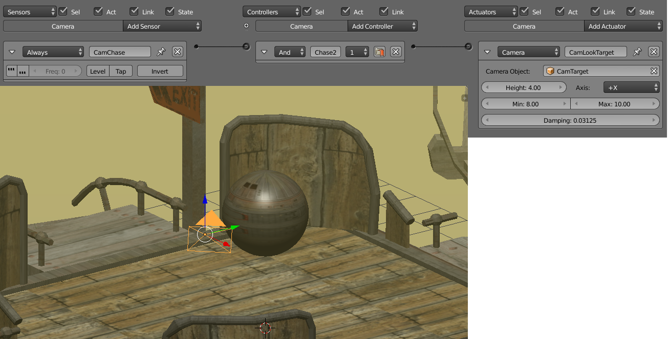
The images below show the logic blocks attached to the Camera Target Empty and the physics applied to it. Because the empty is invisible anyway, there was no need to turn on the invisibility button under the Physics tab.
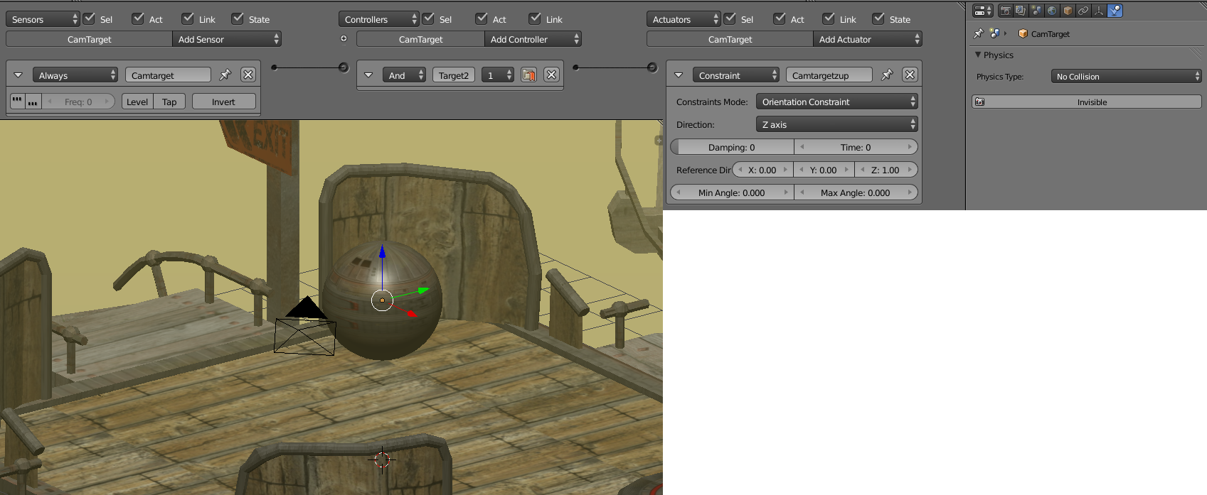
Camera Target Empty - logic blocks and the settings under the Physics tab.
The Camera
The Camera is set up to look at and chase the ball, or more correctly to chase the Camera Target Empty described above. The Axis defines that it will get behind the object it is tracking, and the Height, Min, and Max all define how far away from the object the camera will stay.
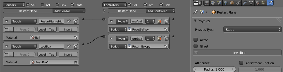
Reset Plane
The reset plane within the Steely Taws Puzzle 1 game (Taws-Puzzl-v2.blend) differs slightly from the Reset Plane used in the first edition and in the “Taws-Core” in that it also responds to the crates should they accidentally fall from the game area. This is achieved with the introduction of another touch sensor which reacts to the box material (Pushbox1) by activating the ReturnBox.py script.
ReturnBox.py
import bge
import mathutils

cont = bge.logic.getCurrentController()
scene = bge.logic.getCurrentScene()
own = cont.owner

Zoom = mathutils.Vector((0.0,0.0,-0.0))

sens = cont.sensors['LostBox']

objList = scene.objects

Box1 = objList['PushBox1']
Box2 = objList['PushBox1.001']
Box3 = objList['PushBox1.002']


if sens.positive:
    Box1Poz = Box1.worldPosition
    Box2Poz = Box2.worldPosition
    Box3Poz = Box3.worldPosition
    #Find out which box it was.  This can be done by
    #finding which box is the lowest.

    if Box1Poz[2] < Box2Poz[2] and Box1Poz[2] < Box3Poz[2]:
        RetBall = Box1
        ResetPozn = mathutils.Vector((-53.85,96.37,-4.8))
    elif Box2Poz[2] < Box3Poz[2] and Box2Poz[2] < Box1Poz[2]:
        RetBall = Box2
        ResetPozn = mathutils.Vector((-53.85,96.37,-4.8))
    else:
        RetBall = Box3
        ResetPozn = mathutils.Vector((31.42,25.36,1.8))

    RetBall.worldPosition=ResetPozn
    RetBall.setLinearVelocity((Zoom),False)
At the time that a box strikes the Reset Plane, this script looks at the positions of all of the boxes in the scene (objects PushBox1, PushBox1.001, and PushBox1.002). The box at the lowest z-position must be the one that has fallen off the game area and so that box is repositioned back to its starting position. In this puzzle PushBox1, and PushBox1.001 are both returned to the same location because they share the same deck, while PushBox1.002 is relocated to its original location on a different deck. The code can easily be expanded to accommodate more boxes.
End of Puzzle
Obviously the end goal of the puzzle is to reach an end point. The end goal looks like this.
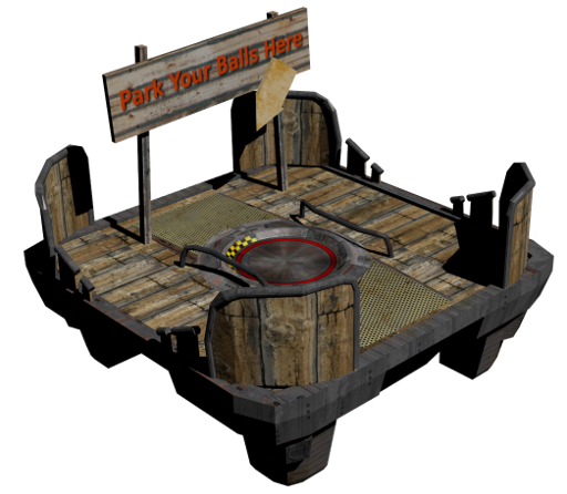
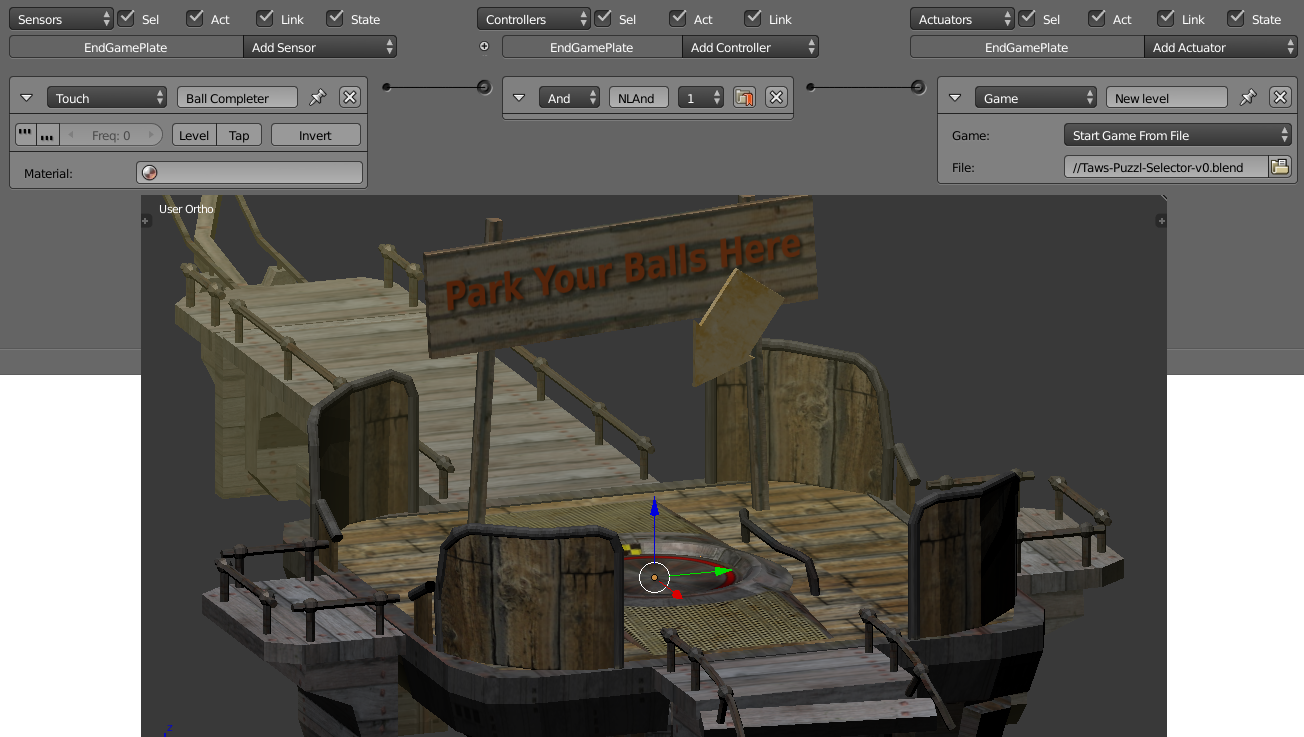
The model for this is “EndSign.blend”. The only active element is the plane in the middle of the pad called “End Game Plate”.
In this edition it responds to anything touching it by loading the new game scene “Taws Puzzl_Selector_V0.blend” so that the user can select the next puzzle along (if there was a next one).
In the case of this first puzzle, the long run of twin rails the player must negotiate to get to this end point means that they are unlikely to be pushing a box over the finishing point. This means we can get away with the End Game Plate responding to anything touching it rather than items carrying the “ball” material. In a more complex scene it may be necessary to restrict this to only responding to the ball – or maybe responding only to something else being pushed onto it if that is the nature of the new puzzle.
Two-Way Automatic Barrier
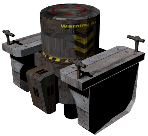
The model for the automated barrier is “Autobarrier.blend”. Because the barrier does not restrict the passage of the ball it is more or less just an active bit of scenery rather than a part of the puzzle.
The touch sensor is set to only respond to the ball material so if the player were to try pushing a box against it they will find that it will not work.
The intention of the logic was to ensure the barrier would activate and run through its animation before rising again after a predetermined time. This complex arrangement was to avoid the strange behaviour that was occurring where the animation was interrupted by another touch and would instantly jump back to the start of the animation often giving the ball a good kick in the process. Great fun, but not the intention of the puzzle.
The logic used achieved this by using the timer property and a flag for when the barrier was already active. While it worked it was also very cumbersome and according to the various manuals, doing it with logic blocks is quite a processor heavy way of doing it. For the other barriers and elevators in the puzzle I found a more elegant way using animations of the whole cycle instead. This is described in more detail in the later sections.
Here are the logic blocks used.
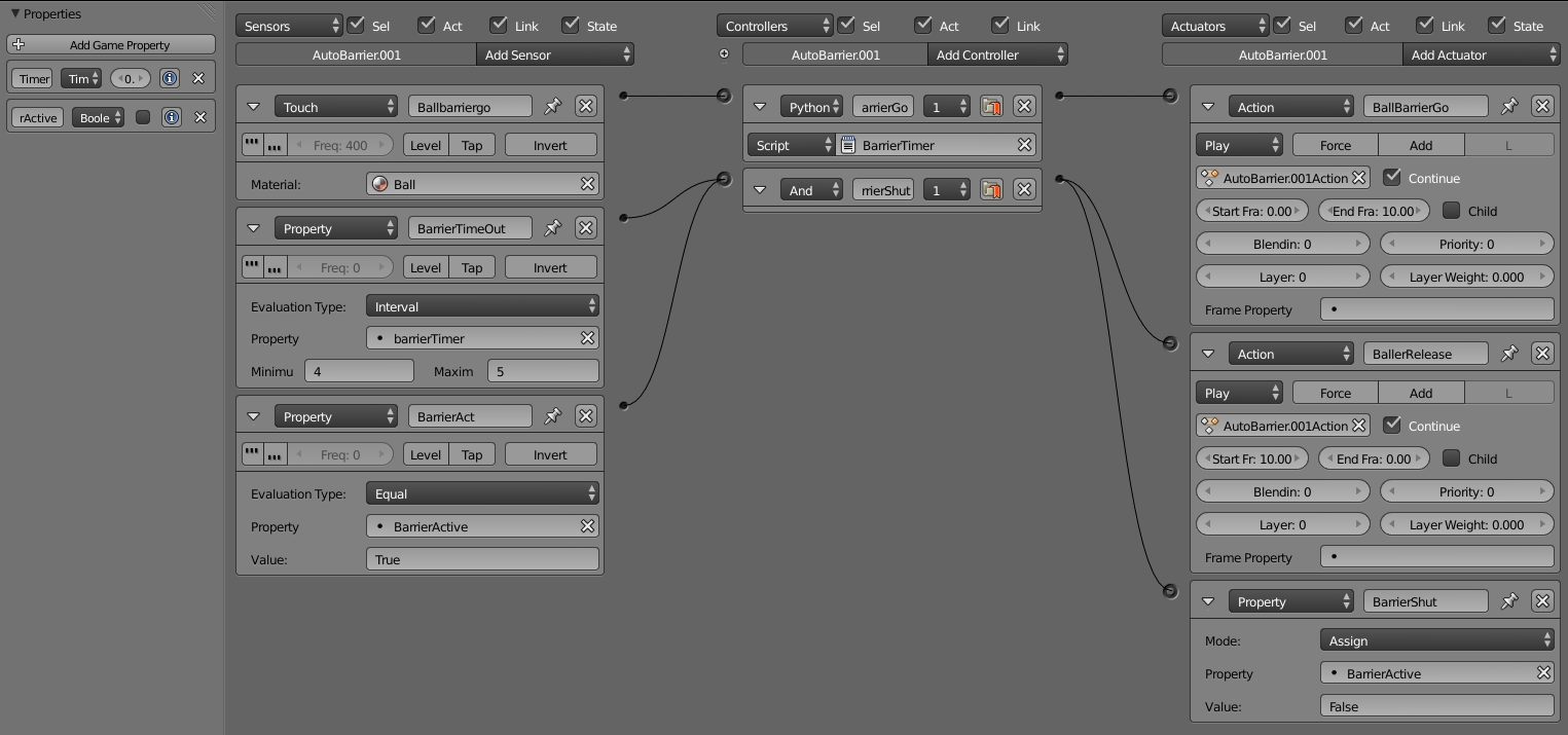
The logic called upon the BarrierTimer python script to control the barrier.
When the ball first touches the barrier, the BarrierTimer script is activated which zeros the Timer property and sets the barrier BarrierActive property to true if the BarrierActive property is not already true AND the Timer has not been zeroed already in the past half second. It then allows the BallBarrierGo action actuator to play the 10 frame animation.
The BarrierTimeOut sensor and the BarrierAct sensor are looking at the Timer property and the BarrierActive property respectively. When the Timer reaches 4 seconds AND the BarrierActive property is True, (the barrier having been triggered) the 10 frame animation is played backwards to return the barrier to the top position and the BarrierActive property is set back to False ready to be triggered again.
By changing the minimum figure in the BarrierTimeOut sensor, the period the barrier remains down can be extended indefinitely. So despite being a bit clumsy this logic arrangement does have some flexibility benefits.
BarrierTimer Script
import bge

cont = bge.logic.getCurrentController()
own = cont.owner
TouchSens = cont.sensors['Ballbarriergo']

barrierDown = cont.actuators['BallBarrierGo']

if TouchSens.positive and own['barrierTimer'] > 0.5 and own['BarrierActive'] == False:
    own['barrierTimer'] = 0
    cont.activate(barrierDown)
    own['BarrierActive'] = True
1-Way Automatic Gate
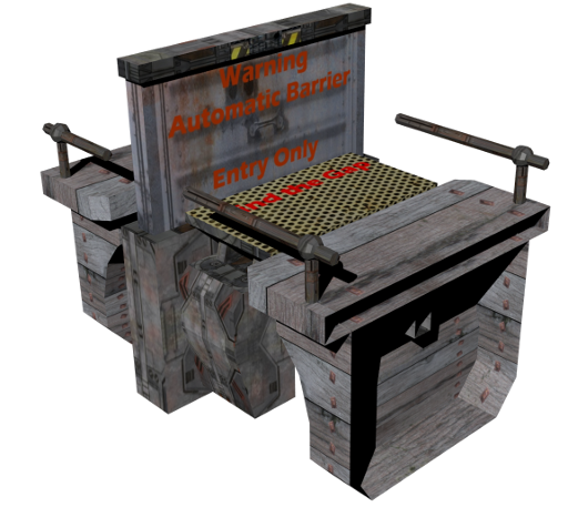
Another style of gate was called for in the puzzle and this was a one-way gate. To make it activate from only one side a “Touch Pad” was added to one side of the barrier which would activate the barrier when something touched it.
In the puzzle there are two gates of this type, one has a short cycle time while the other has a long period during which it is down. The long period for the later one is to allow the player time to push a box across it without the barrier popping back up and throwing the box or player over the end of the game play area.
Where the two-way barrier described above used fairly complex arrangements of timers and logic blocks, the two one way gates make use of a much simpler arrangement where the animation includes the full cycle along with all the necessary dwell times at the top of the motion and the bottom of the motion.
The animations can be described as follows;
|
Frames |
Action |
|
1 - 10 |
The barrier drops down to allow the ball to cross |
|
11 - 59 |
The barrier remains low. |
|
60 - 70 |
The barrier rises back to the original position. |
For the long cycle, the cycle length is
|
Frames |
Action |
|
1 - 10 |
The barrier drops down to allow the ball and box to cross |
|
11 - 439 |
The barrier remains low. |
|
440 - 450 |
The barrier rises back to the original position. |
The logic in both cases is the same. A touch sensor is attached to the Touch Pad on the front side of the gate. When an object touches this a message is broadcast with a message such as “TriggerGo”. On the gate slider object, a Message Sensor is listening for the message associated with its Touch pad. When it hears this message is activates the Action Actuator and plays the animation. To ensure the animation plays through completely without a second touch on the pad resetting it, the Message Sensor is set to Tap. This means that if the ball or box is sitting on the Touch Pad, as is likely to be the case, it will not fire again until the object has moved off the pad and then returns to it once the animation has played through once.
Here are the logic blocks for the long cycle 1-way gate.
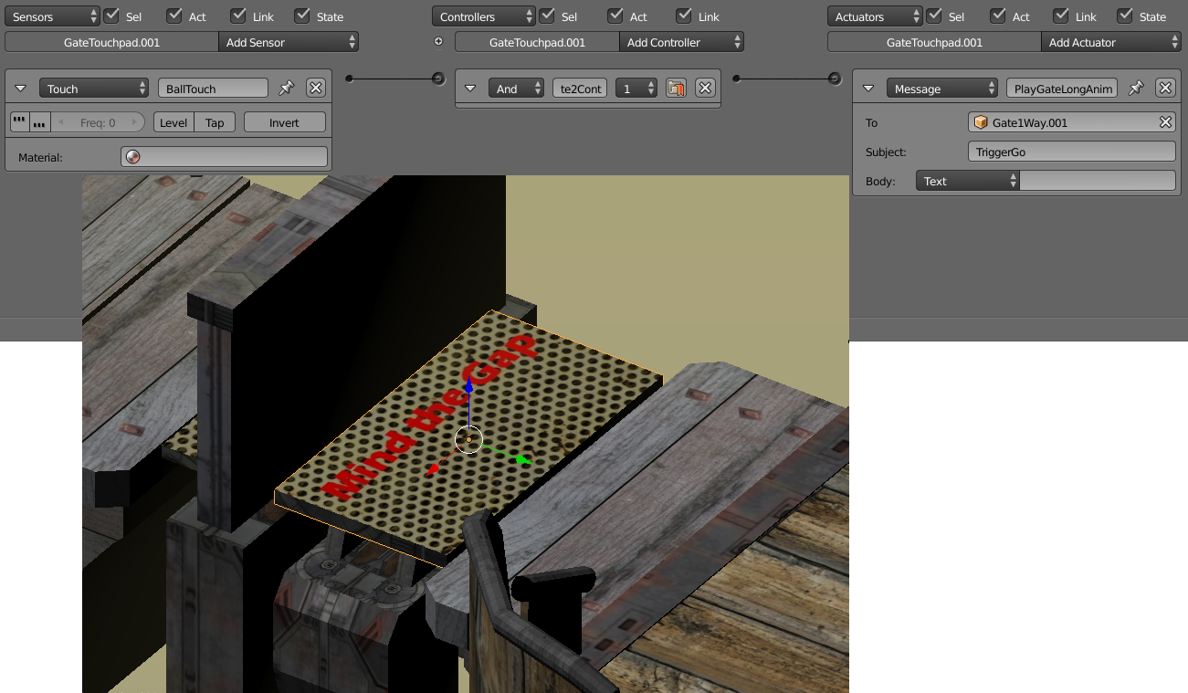
Logic attached to the Gate Touch Pad
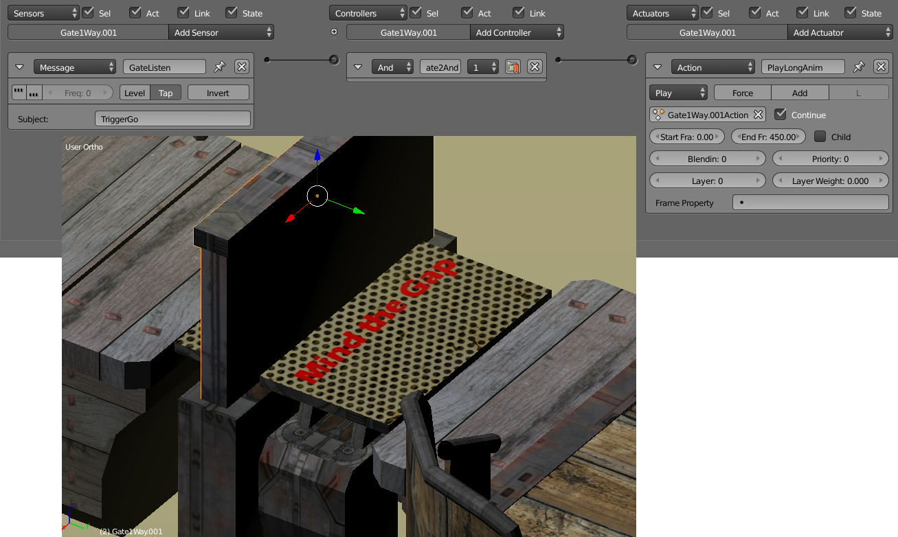
Logic Attached to the Gate.
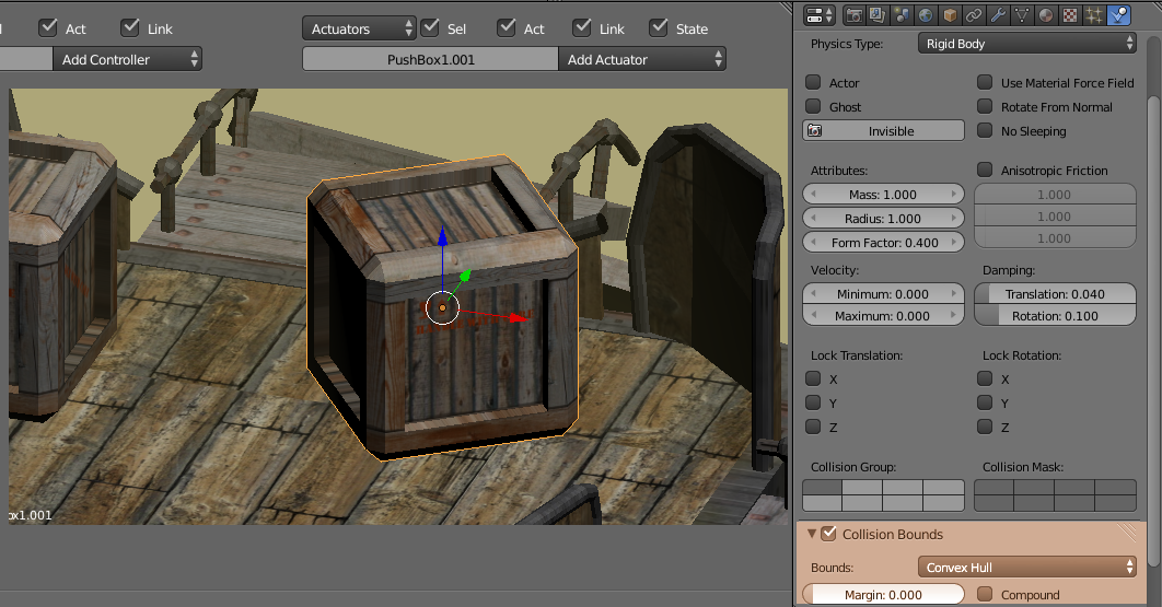
Push Box
A key part to the puzzle are the boxes. They do not have any logic attached to them at present, but may do when sound is added. Because they are objects that physics will be applied to they are defined in the physics panel as a rigid body. While it would have been nice to use the cubic collision bound for the boxes I found that they tended to catch on the small variations in height between the different bits of the geometry. To get around this a Convex Hull was a better approximation of the actual shape which has beveled edges that do not catch on the geometry quite so badly.
Box Trigger
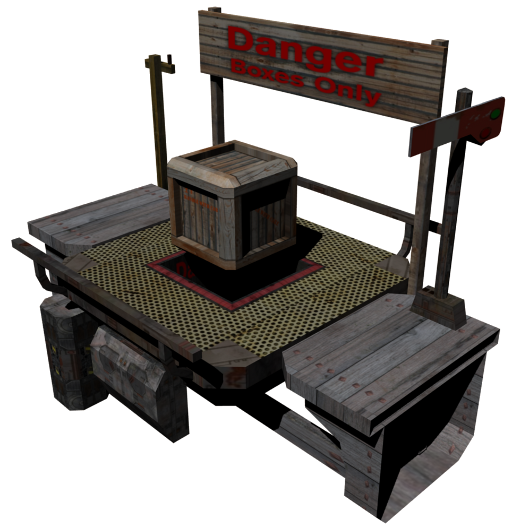
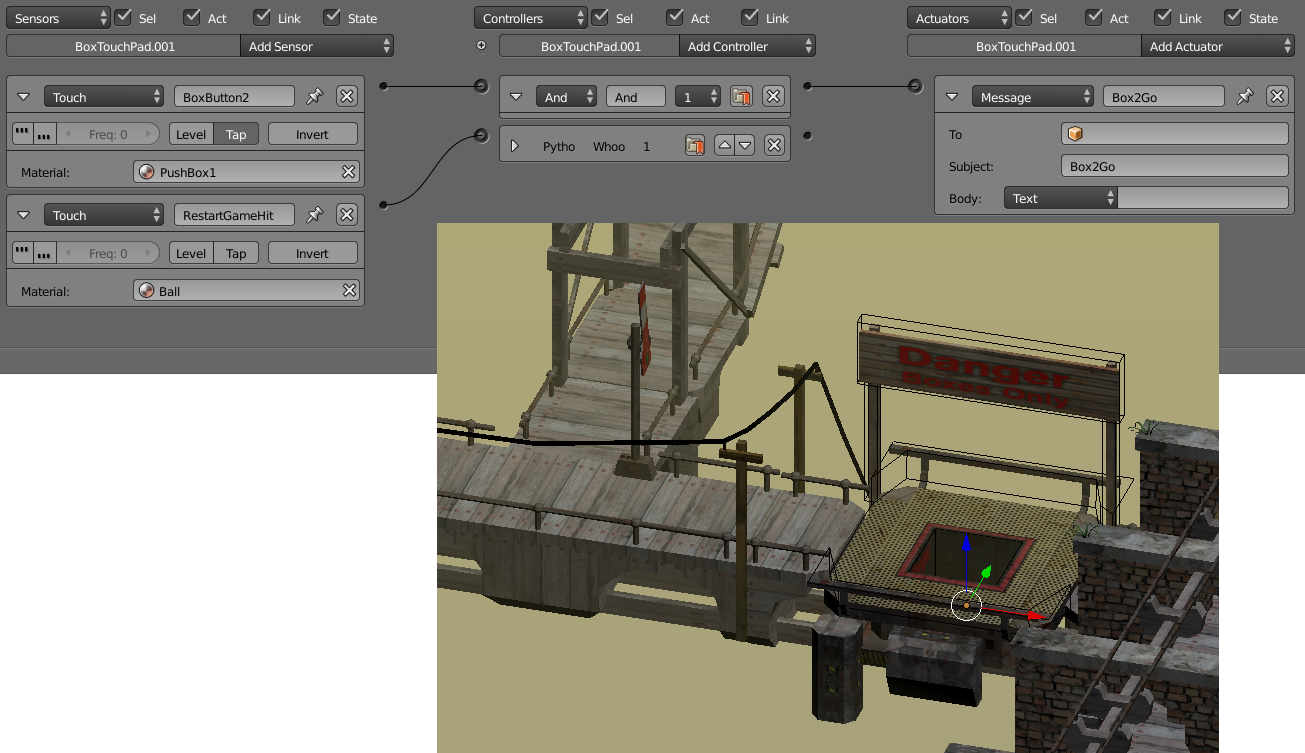
The box is used to trigger events that will remain on. This called for the design of an element that would accept a box and prevent it from leaving once a box had been brought to it. A square hole with a touch sensor on the bottom was the solution. In many ways, the Box Trigger works in much the same way as the Touch Pad on the 1-Way Automatic Gate. At the bottom of the square receptacle is a plane called the BoxTouchPad which has a touch sensor on it that responds to an object carrying the PushBox1 material coming in contact with it by broadcasting a message with the subject “Box2Go” or other message depending on what other actions are to be triggered. To prevent an unplayable situation occurring where the ball falls into the hole and is unable to get out, a touch sensor that responds to the Ball material is also present on the BoxTouchPad. If the ball falls into the hole this logic calls the same python script as the Reset Plane, ReturnBox.py, which drops the ball back to
the starting position.
I found that unplayable situations could occur where the box became located up against the railings of the Box Trigger platform. By adding in some simpler invisible collision geometry and turning off the collisions for the visible geometry alleviated this problem. The collision geometry in the puzzle level has been corrected, but that in the component model has not been updated to work better, so I would suggest you take the collision geometry from the puzzle level and use that if you are intending to make use of this puzzle element.
The logic for one of the Box Triggers is shown below. The collision geometry can be seen as a line around the sign and platform area.
Signal Arm
Associated with each Box Trigger and the button is a Signal Arm rather like a railway signal. This is intended to be a visual cue that something somewhere has changed in response to the button being activated.
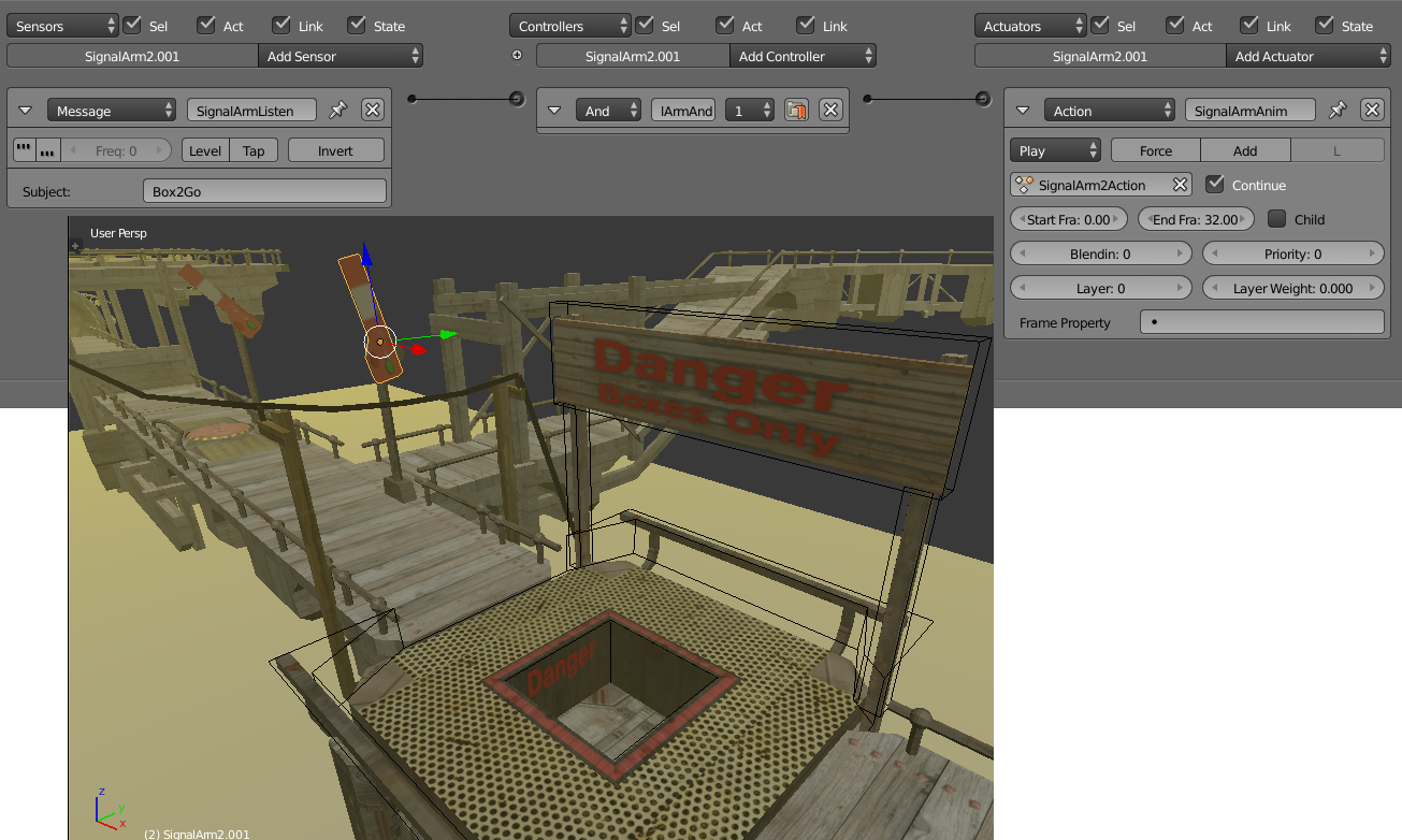
The logic on the arm is very simple. It has a Message Sensor listening for the message broadcast by its associated trigger or button. If it receives this message it runs the animation defined in the Action Actuator, which is just a rotation of the signal arm that takes place over 30 frames.
Draw Bridges
In much the same way as the Signal Arms, the Draw Bridges are listening for their particular message to be broadcast. When they receive it they play an animation. It has a Message Sensor listening for the message broadcast by one of the triggers or buttons. The animation is defined in the Action Actuator, which is just a rotation of the draw bridge section about it’s origin point over 75 frames.
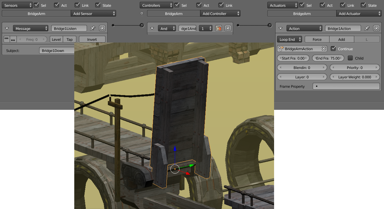
Because the bridges are being triggered by the box-triggers and the box cannot be taken off the trigger, we only need to worry about the bridge going down.
To make it easier for the player to figure out the associations between triggers and draw bridges, power poles and power lines have been added to make a visual link between the two elements.
Constantly Running Elevator
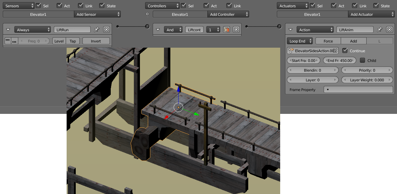
To prevent the player getting trapped in the lower level part of the puzzle and providing a little bit of interest, an elevator was added that was constantly running.
The logic for this element is very simple. An Always Sensor ensures the elevator is running at all times. To keep the logic very simple, the animation that is being played in a loop through the Action Actuator, is a 450 frame long cycle with long dwell periods at the top and bottom of the motion. To allow the elevator to go through its complete cycle without interruption by triggers from the Always Sensor the animation is set to Loop End.
|
Frames |
Action |
|
1 - 75 |
The elevator rises to the top level over 3 seconds (75 frames) |
|
76 - 225 |
The elevator remains at the top position for 6 seconds (150frames). |
|
226 - 300 |
The elevator drops to the lower level. |
|
301 - 450 |
The elevator remains at the bottom position for 6 seconds |
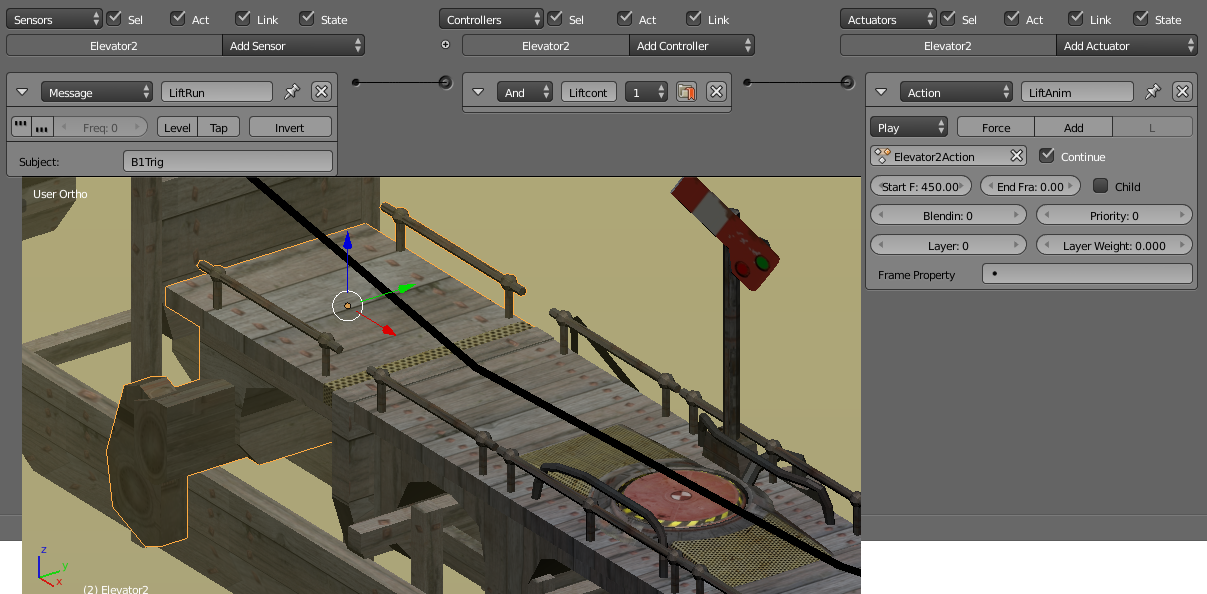
Triggered Elevator
In exactly the same way as the Draw Bridges, the triggered elevator is listening for a message that will activate it and cause it to run through an animation cycle defined in its Action Actuator. The difference in this case is that the animation only plays once each time the associated button is touched and although the animation sequence is the same as for the constantly running elevator, there is a 6 second dwell at the bottom level before it rises. This is to allow the player to figure out what they have triggered and also to get onboard before it goes up. The dwell is achieved by playing the animation sequence in reverse, thus the start frame is 450 and the end frame is 0.
Touch Button
Several types of buttons were created for the game but in the end only one was used and this was the type that would send a message when the ball touches it, play an animation to make it sink in response, then rise again to reset ready for another touch. Because this was the first active element developed for the game has relatively complex logic to achieve something that is quite simple and has been achieved more efficiently with the methods described for the elevators and the one-way barriers.
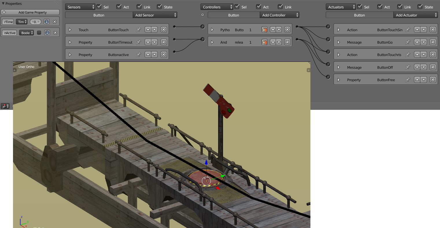
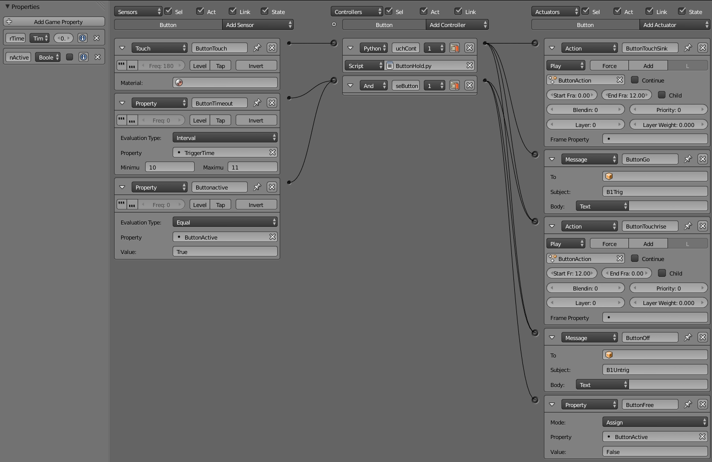
Logic blocks expanded for easy reading.
There are two properties associated with the button, a Timer and a Boolean called ButtonActive to flag whether the button was already “busy” or not. There is also a 12 frame long animation comprised of only two key frames; one at the top position and one at the depressed position. In hindsight, animating the full motion including dwell periods would have been a better way of doing it because this would have eliminated the complex logic, the ButtonHold.py script, and the need for the properties.
When an object touches the button, the ButtonHold.py script runs but only if the Timer is greater than 0.5seconds and the button is not already down. This “debounces” the button so that the button does not quickly reset and kick the ball into tomorrow. If the conditions are satisfied the animation defined in the ButtonTouchSink Action actuator is played, and a message with the subject “B1Trig” is broadcast. The script also resets the Timer. The python controller is also connected to ButtonTouchrise action actuator and the ButtonOff message actuator both of which are not used by the script so those links are unnecessary unless more complex behaviour was desired such as running the rise and fall entirely within the python script.
Once the Timer gets to between 10 and 11 seconds, AND the ButtonActive flag indicates that the button is in use, the controller to reset the button position activates the ButtonTouchrise action actuator to play the animation in reverse, broadcast a message “UnTrig” to indicate that the button is deactivated, and to reset the ButtonActive flag to “False” so that the button can be triggered again.
ButtonHold.py
import bge

cont = bge.logic.getCurrentController()
own = cont.owner
TouchSens = cont.sensors['ButtonTouch']

ButtonRise = cont.actuators['ButtonTouchrise']
ButtonFall = cont.actuators['ButtonTouchSink']
ButtonMSGOn = cont.actuators['ButtonGo']
ButtonMSGOff = cont.actuators['ButtonOff']


if TouchSens.positive and own['TriggerTime'] > 0.5 and own['ButtonActive'] == False:
    own['TriggerTime'] = 0
    cont.activate(ButtonFall)
    cont.activate(ButtonMSGOn)
    own['ButtonActive'] = True
Hopefully this will have adequately explained how the various game components work, to enable you to construct your own puzzle levels using this stuff as a basis.

Note:
The Steely Taws game and components presented here by Hamish Trolove are licensed under a Creative Commons Attribution-NonCommercial-ShareAlike 4.0 International License.

All images and artwork presented on this page are Copyright Hamish Trolove 2015.