Parametric Railway Tracks
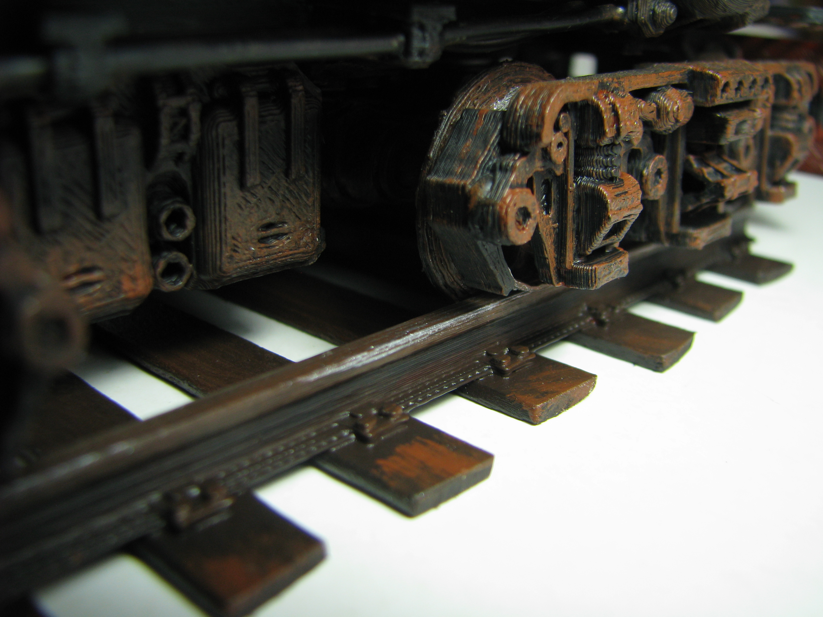

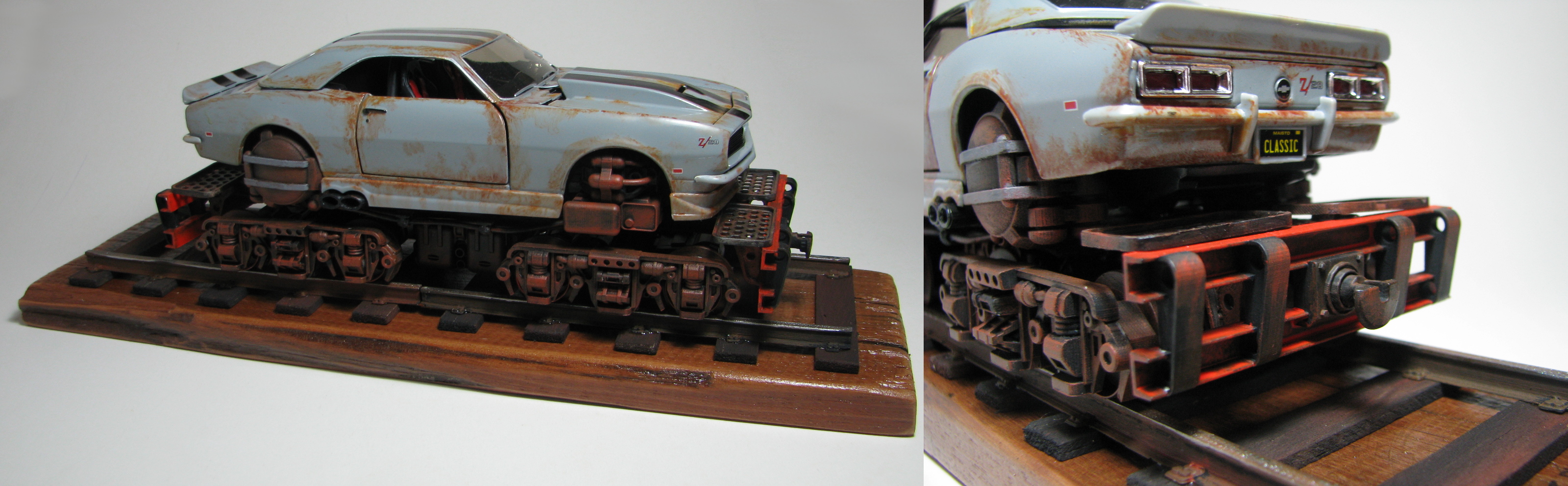
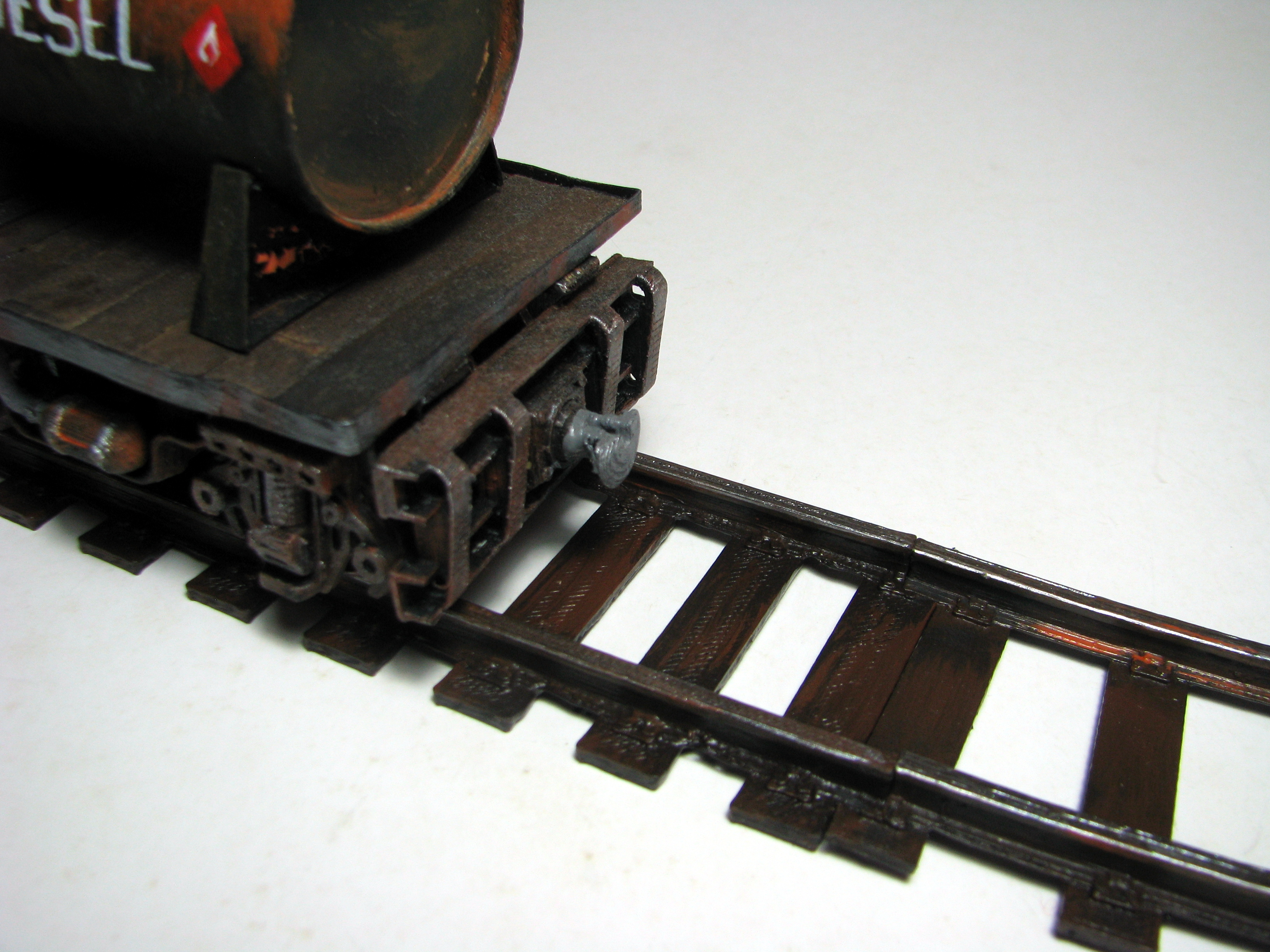
The other week I was contacted about my Railcar chassis design on Thingiverse. The correspondent was wondering if I had any tracks to go with it. I didn’t and so pointed them towards the opensource railway models elsewhere on Thingiverse suggesting they could easily be adapted to fit the gauge I had designed my models for. This exchange got me to thinking about tracks for my models. The rails I have made for my models have generally been wooden which allowed me to make much longer lengths than would be possible with my 3d printer. However on a couple of occasions I have designed and 3D printed some short rail lengths for displaying the models I have given to other people. Wooden rails are fine, even essential, for animation where long runs are necessary and fine detail isn’t. But for display, the 3D printed rails win with their greater detail.

So I was prompted to design some new tracks but wanted to make them parametric so that I could do any gauge I liked. With the existence of the Opensource Railway projects, it made sense for me to design a variation which would be compatible with them. This article describes the parameters for the different models and provides the OpenSCAD files to generate your own tracks.
If you’d prefer to use the Thingiverse customiser interface, links to the different customiser models are provided below too.
Some general things
The Rail Profile
The rail profile I have used has an overall shape that has a quite square bounding box. The rail height equals the base flange width. The bearing surface where the wheel run is half the width of the bounding box. The illustration below will hopefully make this clear.
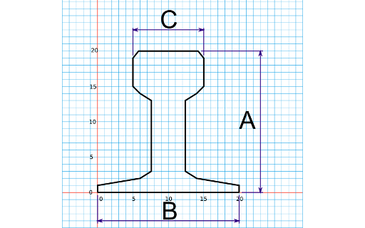
A = Rail height
B = Rail flat bottom width
C = Rail head width
A = B
C = A/2
The profile is described in the line;
polygon(points=[[-0.5,0],[-0.5,0.05],[-0.2,0.1],[-0.125,0.15],[-0.125,0.65],[-0.2,0.7],[-0.25,0.75],[-0.25,0.95],[-0.2,1],[0.2,1],[0.25,0.95],[0.25,0.75],[0.2,0.7],[0.125,0.65],[0.125,0.15],[0.2,0.1],[0.5,0.05],[0.5,0],[-0.5,0]],center = true,convexity = 10);
This is just the coordinates of the shape shown above reduced to a shape 1mm high x 1mm wide. I have used the RailHt parameter in the OpenSCAD code to scale this shape to the desired size. Where things will be a little tricky for anyone trying to reverse engineer the OpenSCAD code to use a different profile is that I have used RailHt to represent the rail flat bottom width (B) and the rail head width (C) using the relationships above. Is used throughout the OpenSCAD code. If you are looking to use a new rail profile that does not have a square bounding box then a bit of untangling will be required.
The General Parameters
There are a number of parameters that are common to all the OpenSCAD model variations presented here.
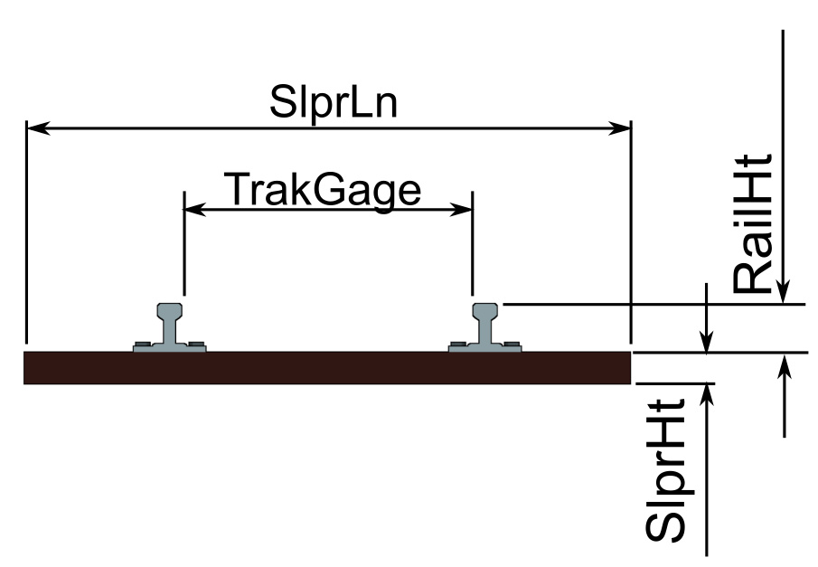
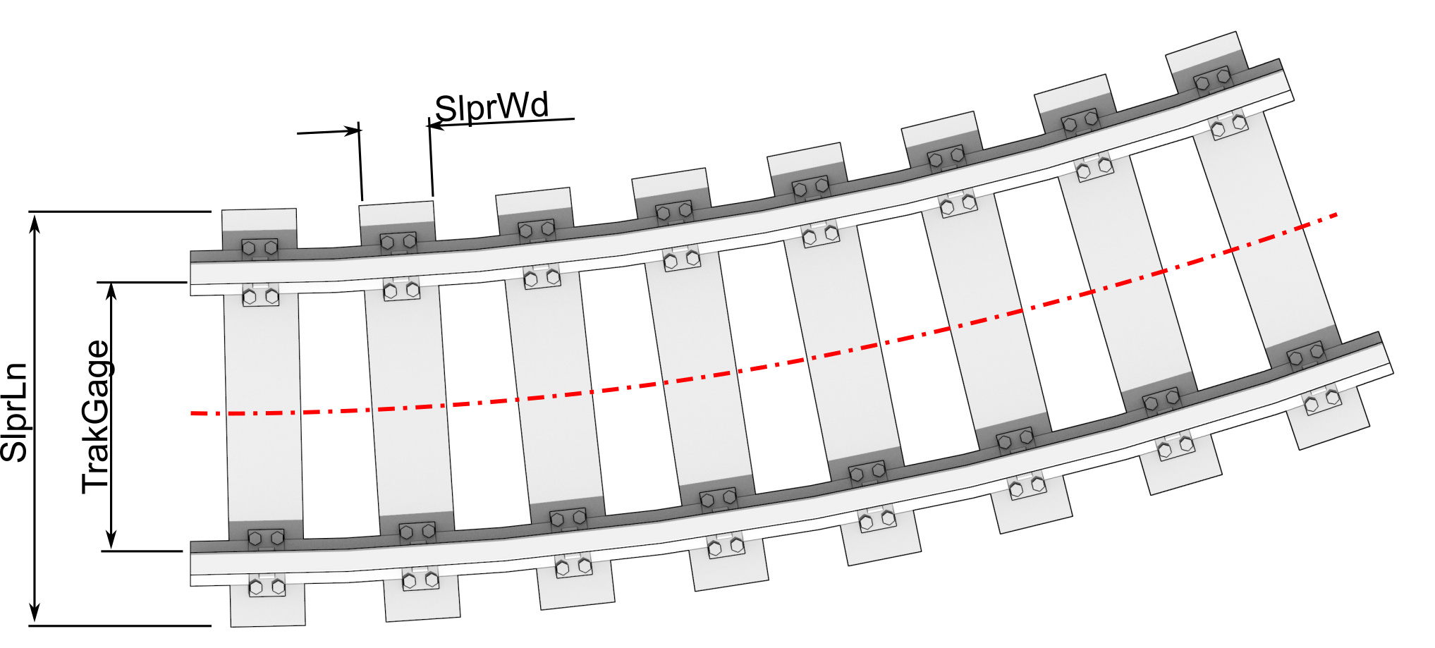
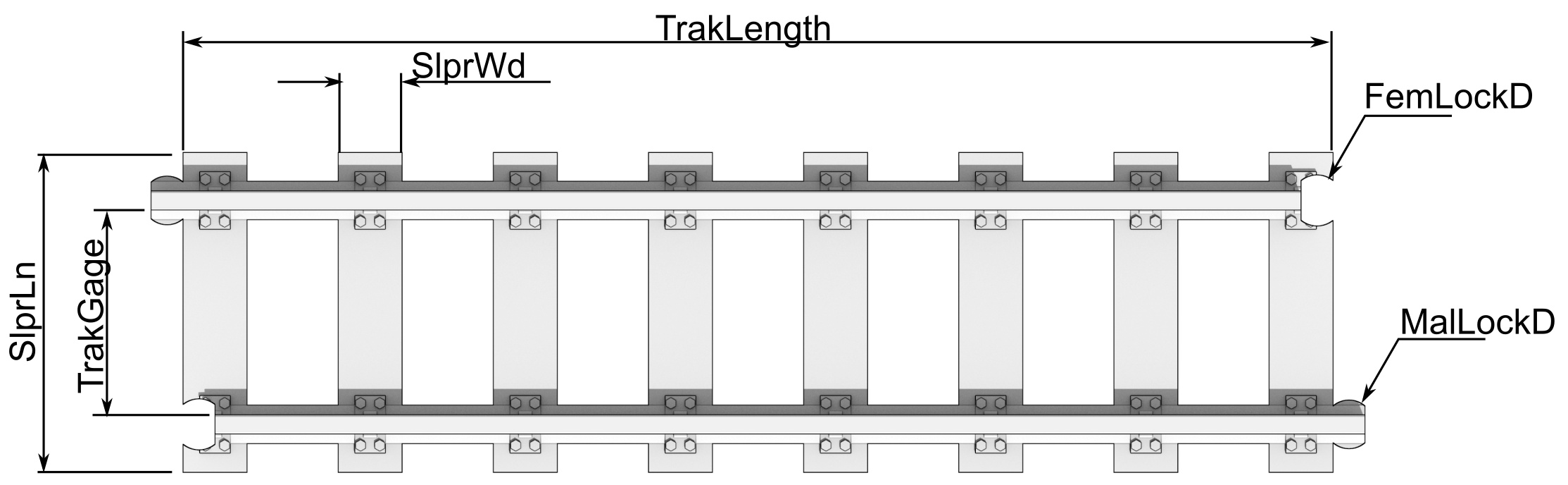
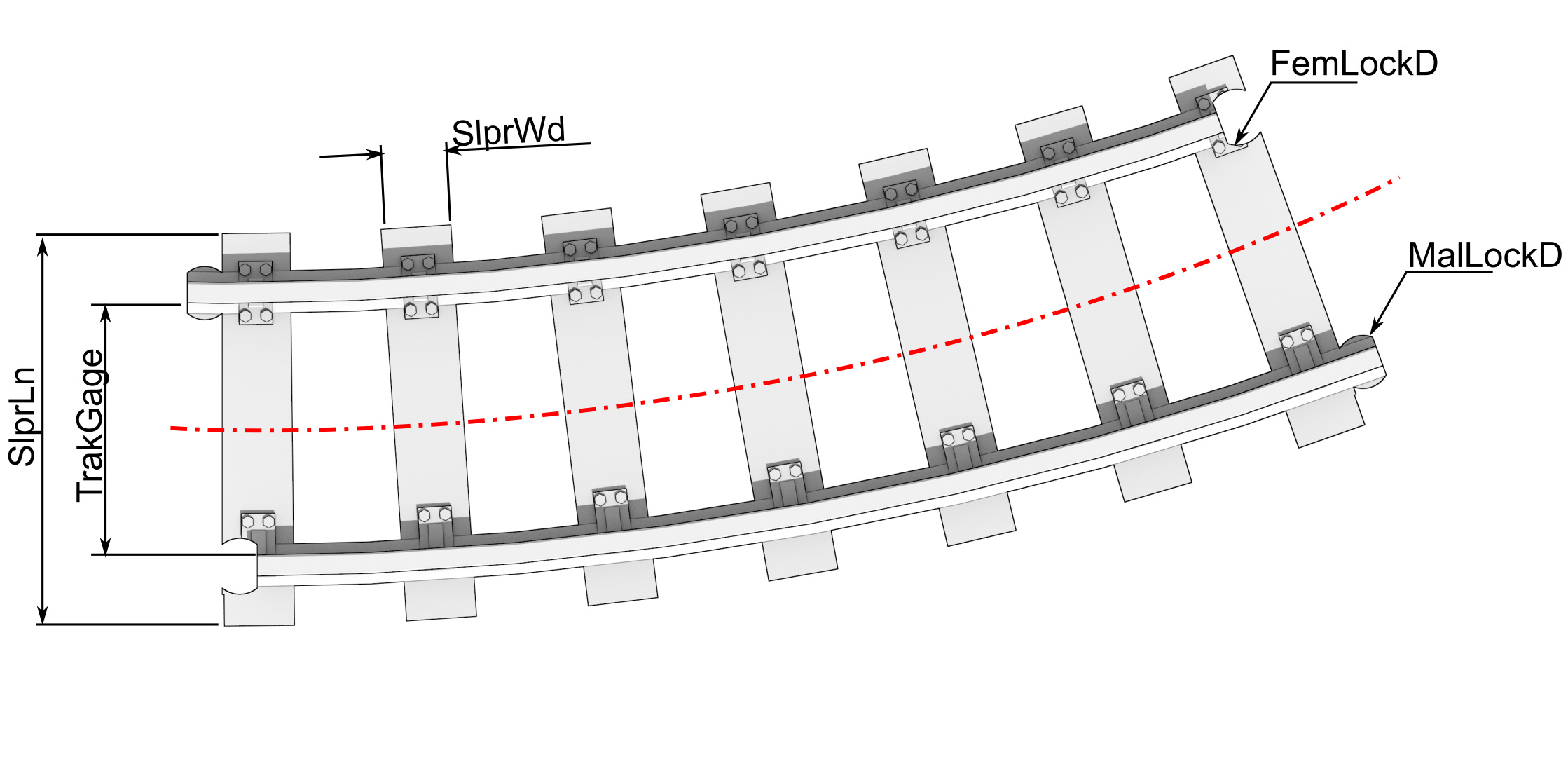
RailHt= Height of the RailTrakGage= Track Gauge. This is the distance between the inside edges of the rail head NOT the distance between rail centrelines. For the Opensource Railway, this is 32mm. For my narrow gauge models it is 36mm, and for my 1:24 railcar chassis models, it is 60mm.SlprLn= Sleeper lengthSlprHt= Sleeper height
SlprWdis the width of the sleepers.NoSlprsis the number of sleepers in the section of rail to be produced.
Straight Track Parameters
For the straight track models the only additional parameter is the track length (TrakLength). In the case of the plain track model, this is the final length of the printed track. The OpenSource Rail total model length is a touch longer because of the connectors, so you will need to allow for that when trying to maximise the model length to match your printer.
Curved Track Parameters
There are two parameters specific to the curved track models. They are;
CurveRad= Radius of railway centrelineCurveSegAng= The angle of the track segment being produced. You will need to choose this to suit your printer bed size.
End Types and Options
There are several options for the plain track models. These are whether or not you have sleepers, and where the join between tracks should appear.
TrkTyp = Type of track end style.
- Setting
TrkTyp= 1 will select the option where the track join is between the sleepers. - Setting
TrkTyp= 2 (or anything other than “1”), will select track type 2 where the join is down the centre of one of the sleepers. This is especially useful if you opt not to print sleepers.
SleepersYN is a flag for having sleepers or not. Setting this to “1” will generate a model complete with sleepers. Setting it to anything else will produce a model that doesn’t include sleepers but includes the sleeper attachment pad details.
OpenSource Railway Connector Parameters
The OpenSource Railway tracks appearing on Thingiverse are connected with a male and female lug on the ends. The parameters for these are;
FemLockD= OS Railways System Female Connector Diameter. Standard size for this is 8mm.MalLockD= OS Railways System Male Connector Diameter. The standard size for this is 7.8mm.
I have found that the tolerance was a bit tight at the standard size so I have the MalLockD default set at 7.6mm. This reduces the fiddling around with a fine file to get it to fit. If you are using a fine nozzle you will probably be able to set this back to that standard OS Railway size.
NOTE: The standard OpenSource railway track has a 2mm wide rail head width while the profile used here has a 3mm rail head width when the rail height is scaled to 6mm to match the standard OpenSource railway track height. Because the connecting lugs are positioned on the centreline of the rails this means there is a ½mm connector position mismatch between the models produced with this parametric model and a standard OpenSource railway component you might pull off Thingiverse. You may have to do a little bit of work with a file to get them to connect if you are trying to connect in a large number of the two types. Other than that they should match seamlessly.
For a Parametric Turnout model you can find out all about them here; Parametric Turnout Model
The Models
Straight Track
The OpenSCAD file for this can be downloaded here: Parametric_RailsLinesv1.scad
For the Thingiverse Customiser version go here: Standard Straight Track
Curved Track
The OpenSCAD file for this can be downloaded here: Parametric_RailsCurvev1.scad
For the Thingiverse Customiser version go here: Standard Curve Track
OpenSource Railway Compatible Straight Track
The OpenSCAD file for this can be downloaded here: Parametric_RailsLines_OSRailv0.scad
For the Thingiverse Customiser version go here: OS-Railway Straight Track
OpenSource Railway Compatible Curved Track
The OpenSCAD file for this can be downloaded here: Parametric_RailsCurve_OSRailv1.scad
For the Thingiverse Customiser version go here: OS-Railway Curved Track
But Wait! There’s More!
Because I was in the OpenSCAD zone, I decided to quickly develop a parametric model for a tool to set the rail spacing. If you are printing the rails without the sleepers, sooner or later you will want to set them in place somehow. Previously I have used a piece of cardboard cut to the right width, laid everything out carefully, and placed a piece of wood with some weight on it while it was gluing. Often the act of placing the wood and weight on would shift the rails and you’d have to have another go. So a correctly shaped and precisely made tool for setting the rail spacing and holding it while it was glued seemed like a good idea.
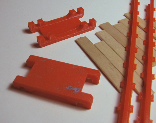
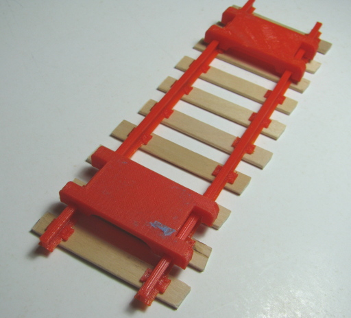
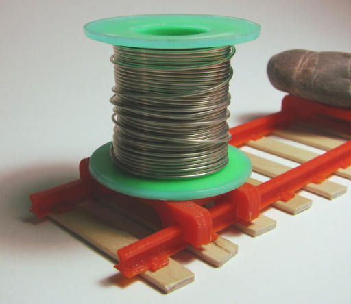
Here are two parametric rail spacing tools. The first one is just a spacing tool, while the other is designed to have heavy items placed on it to help hold the tracks in place while glue sets.
Simple Spacing Tool
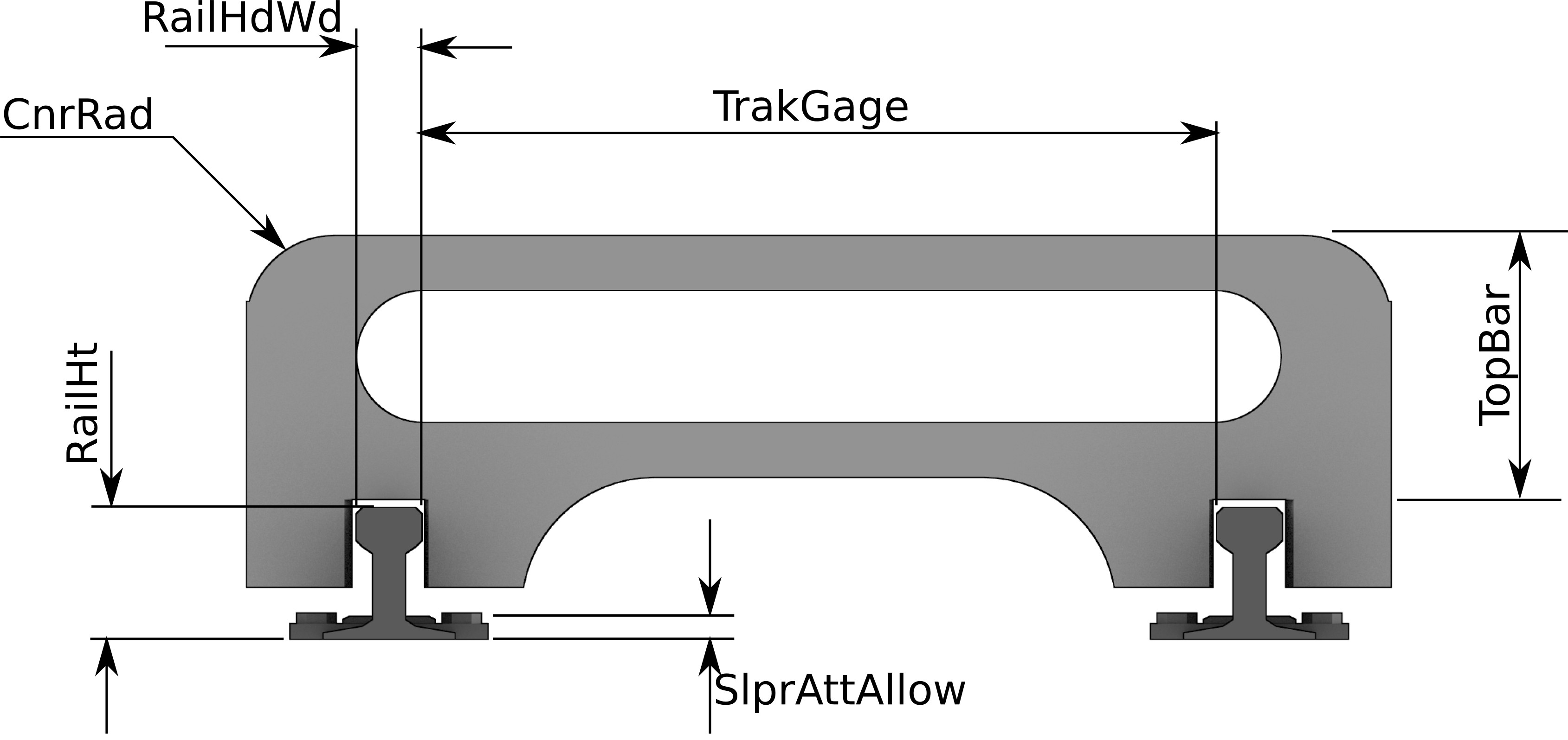
The diagrams below introduce the variables used in the OpenSCAD model file which can be downloaded from here: TrackGaugev2.scad
Spacing and Setting Tool
The diagrams below introduce the variables used in the OpenSCAD model file which can be downloaded from here: TrackGauge-WeightDeckv2.scad
The OpenSCAD models do not include any safeguards for daft selections of parameters. If you find you are getting unexpected results, check your parameters.


This design by Hamish Trolove is licensed under a Creative Commons Attribution-ShareAlike 4.0 International License.