Parametric Footplates
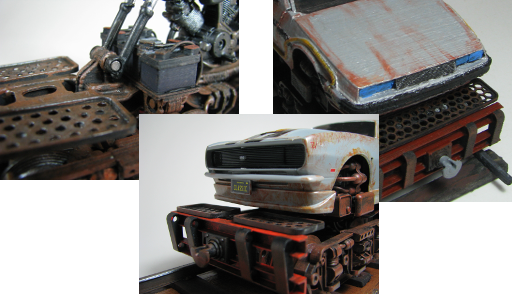
I have used grid type footplates on a number of my projects such as the Railbike and the Rail car model. The original footplate was designed by my partner who was bored and looking for a quick thing to design. I reused this model many times and manually adjusted it if I needed a different size. This was a tedious process and meant that I tended to stick with only a couple of different sizes. With the Rail car model I suddenly decided that it was high-time that I made an OpenSCAD parametric version of the footplate. This now meant I could use it for generating different mesh densities, aperture sizes and even aperture shapes.
The hexagonally packed aperture parametric model used for hexagonal apertures and shapes with higher numbers of sides was modified slightly to produce models for generating square and diamond shaped grids.
Here are links to the OpenSCAD scripts and their location on Thingiverse. If you use the Thingiverse customiser links you won’t need OpenSCAD to generate STL model files for 3D printing.
Downloads and Links
The scripts below will work on quite old versions of OpenSCAD because it doesn’t use anything other than the basics to generate the shapes. No extra libraries are required.
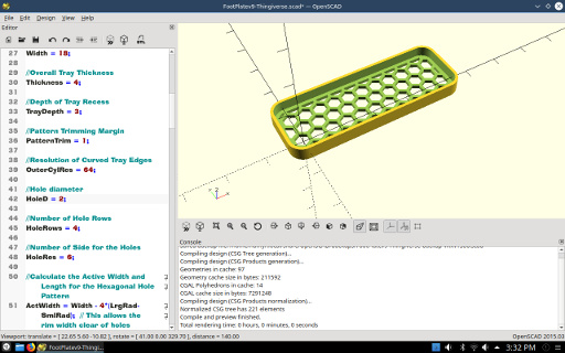
Hexagonal Pattern Footplate
You can find the hexagonal-circle pattern footplate here: FootPlatev9.scad
and on the Thingiverse Parametric Footplate webpage.
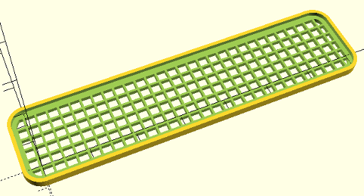
Square Pattern Footplate
You can find the square grid version here: FootPlateSqrv0.scad
and on the Thingiverse Parametric Footplate - Square Grid Pattern webpage.
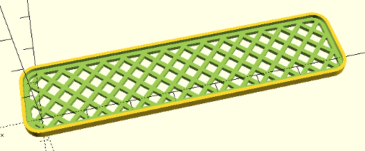
Diamond Pattern Footplate
You can find the diamond pattern version here: FootPlateDiamondv0.scad
and on the Thingiverse Parametric Footplate - Diamond Pattern webpage.
Using the OpenSCAD Script
Here is an explanation of the various parameters used in these OpenSCAD scripts.
Basic Tray Dimensions
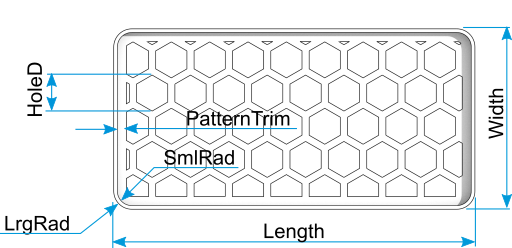
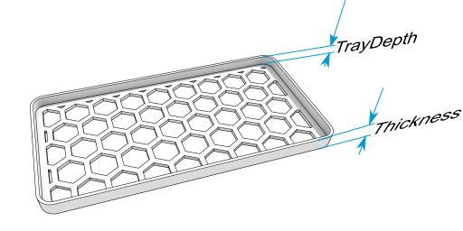
The overall shape of the footplate are governed by the following parameters.
LrgRad: This is the outer corner radius.SmlRad: This is the inside radius of the tray corner.Length: The overall length of the footplate.Width: The overall width of the footplate.Thickness: The overall thickness of the footplate and footplate rim.TrayDepth: The footplate rim height above the footplate deck.PatternTrim: This parameter governs the space between the inside of the rim and the start of the hole pattern.OuterCylRes: This is the resolution of corner curves. The default of 64 produces a fairly smooth curve.
Aperture Parameters
The grid holes are controlled by the following parameters;
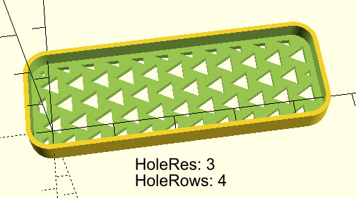
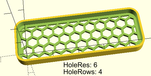
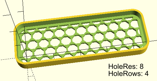
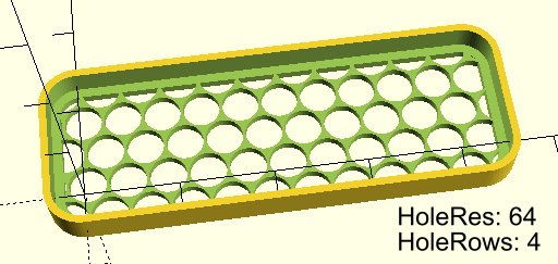
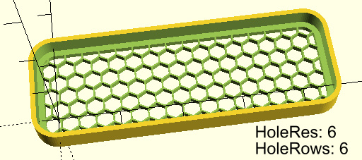
HoleD: Hole diameter.HoleRows: This is the nominal number of hole rows across the width of the footplate. It is not linked to the hole diameter and the user will need to adjust the hole size to match the number of rows, the width of the footplate, and the look they are after.HoleRes: (Hexagon pattern footplate only) This parameter controls the number of sides each hole has. This gives the user a range of shapes from triangles to very smooth circles. Please see the examples below.
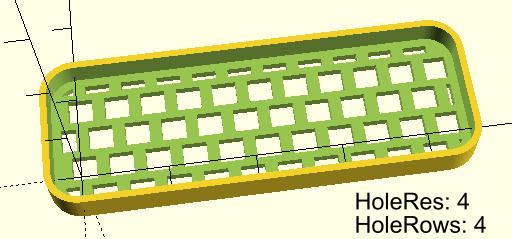
This one looks a bit dumb with the hexagonal packing. Use the Square version instead.
The OpenSCAD models do not include any safeguards for restricting the holes sizes and corner radii to be plausible so if you find the grid has disappeared or your rim is gone, check the relative sizes of your Outer and Inner radius and the holes sizes.


This design by Hamish Trolove is licensed under a Creative Commons Attribution-ShareAlike 4.0 International License.