3D Printed Railbike
A little while ago I posted a set of 3D printed railway bogies with the intention of incorporating them into a larger project. One of the larger projects was to build a deck and attach a 1:18 scale motorbike model from Maisto. This article describes the project and provides all the 3D printable models.
Just to reiterate this last point: THIS MODEL DOES NOT INCLUDE THE MOTORBIKE. The motorbike featured is an old Maisto model I bought years ago. There are some good 3D printed motorbike models around that might lend themselves to this project.
- Hex17 has a nice one here: Thingiverse Thing 2248854
- and also Valcrow’s super detailed Ducati model can be found on Youmagine: Ducati 1199 Superbike
Here are some early concept images of what I had in mind. Because of its over-the-topness, the articulated version appealed more and so was the design I followed through with.
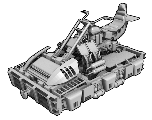
An early Rail-bike - The original 6-wheeler concept
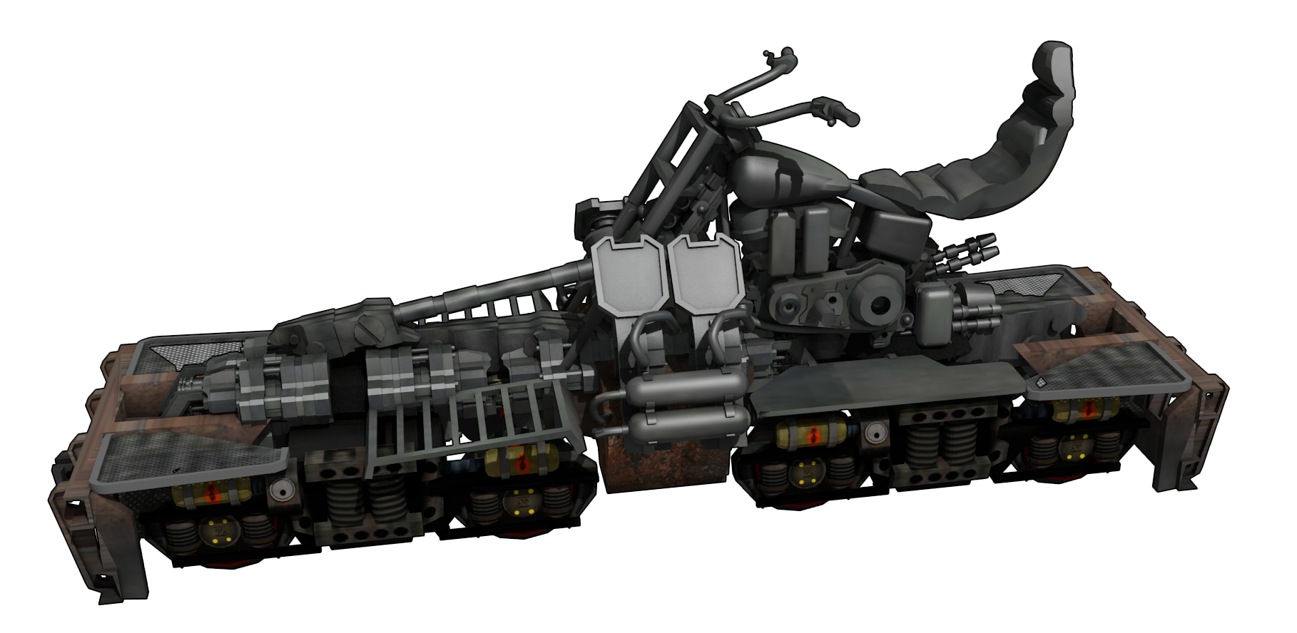
A completely over-the-top articulated rail-bike concept
I was keen to make something that looked like a plausible vehicle. The design theme I was working with was an arrangement that could be constructed from common old equipment lying around and able to be maintained easily in the field. There were three options I considered; mechanical drives, hydraulic or pneumatic drives, and electrical drives.
- Mechanical drives: This option would use drive shafts to the bogies and have some chain drives, bevel gears and such to get the motion to the wheels. There were two arguments against this as a good design; the gears and shafts would need to be quite specifically manufactured for the vehicle, and the motorbike motor, gearbox and clutch would probably have a hernia when the drive was engaged because of the weight of the chassis. So this was dropped out of my considerations early.
- Hydraulic or Pneumatic drive: There are plenty of examples of internal combustion engines driving hydraulic motors especially on heavy vehicles like locomotives, and earth moving equipment. This would allow the motorbike’s engine to run at an output that suits it better. The motorbike’s engine would drive a hydraulic pump located where the rear wheel was. The hydraulic motors mounted in the bogies can be quite compact and the hydraulic fluid can be piped around thereby avoiding any complication around the bogie connections. The downside of hydraulics and pneumatics was that it wasn’t stuff you would necessarily find a lot of. I also felt that if it failed in the field it would be game over. There would be no way of jury-rigging a repair.
- Electrical drive: The electrical drive is a series hybrid with the motorbike motor driving a generator. The generator would output electricity to the charge controller which would distribute it to the battery bank. The charge controller would also send electricity to the capacitors under the frame which would feed into the motors on each bogie set. This is a common enough type of arrangement with hybrid vehicles. There are lots of electric motors out there, cables can be found easily and components for charge controllers are also relatively easy to come by. In the field it is also possible to effect a repair with a bit of metal or substituting something similar. So electrical drive was the solution to carry into this design.
Having decided to use an electrical drive as the basis I designed the hardware around that and used wire to model the cables running between the different components. I have no doubt that any electrical engineers looking at this will probably take umbrage to some of the things I have done but hey, it’s a fictional model. Sure, yes, in this model I have two cables from the motor to the charge controller rather than three – the rectifier is in the box mounted on the motor, OK?
Anyway, I strongly suspect that a Harley Davidson engine is not going to be powerful enough to shift the railbike chassis along let alone pull a line of wagons as well. Something Japanese might do it though.
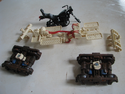
The 3D Printed Bits and Materials
The image below shows the 3D printed model bits.

You will find the model files are all of the format “3DPrintedRailbike-Blahblahblahx4.stl” where the last bit is the number of that item you will need to print. So yep, you can expect quite a pile of pieces by the end of your printing session. None of the pieces require support.
The extra bits you will need are;
- a pair of M4 machine screws and a nut. You may like to include a washer.
- some Ø4mm dowels 54mm long (or anything else you can use of an axle)
- a short Ø4mm dowel to pin the two sides of the deck spine together
- hook up wire and any wire about Ø2mm for the cables
- some Ø3 rod of some sort to pin the motorbike model to the locations on the deck. I used some bits of old nail.
- Your chosen motorbike model
Here are the models:
- The STL files: 3DPrintedRailbike-STLs.zip
- The blender model: 3DPrintedRailbikev4-blend.zip
- An obj model of the assembled model for those using other modeling packages: 3DPrintedRailbikev4-obj.zip
You can also get the same model from Thingiverse or Youmagine if you would prefer;
Assembly
There are two stages in the assembly; the bogies, and the deck. You can find these assembly instructions as a pdf here: 3DPrinted_Railbike_Assembly_Instructions.pdf
Assembling the Bogies
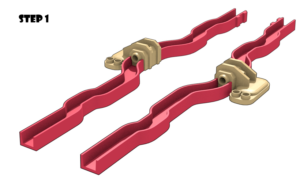
Step 1
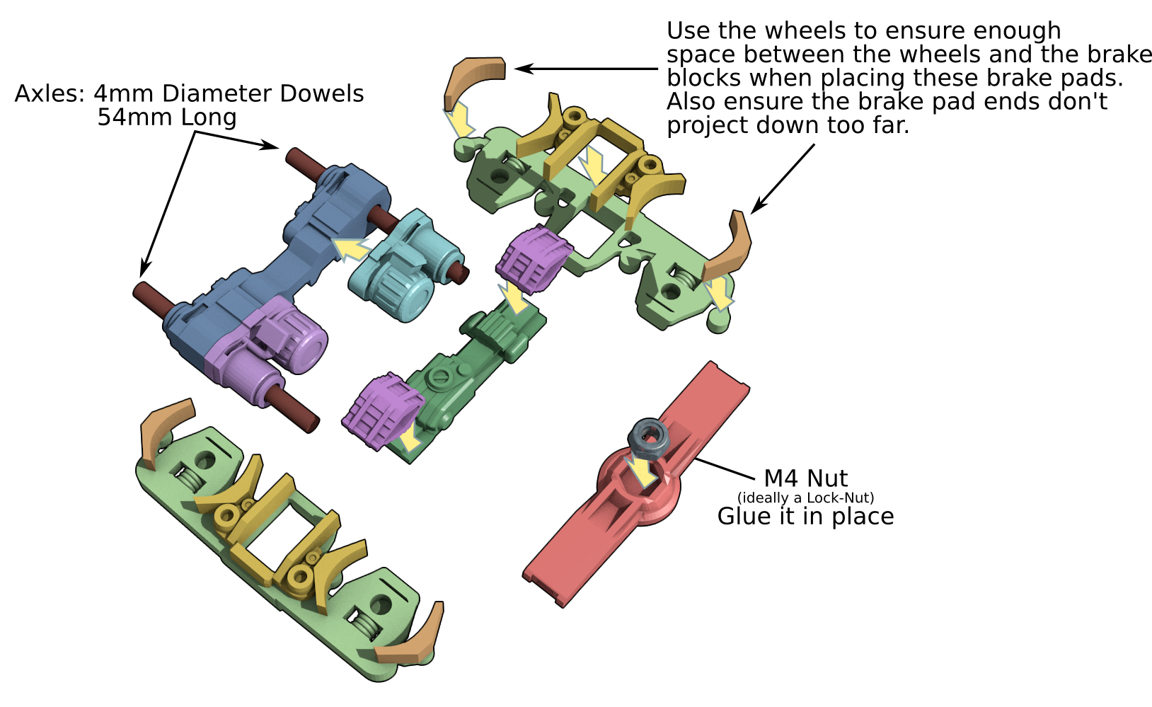
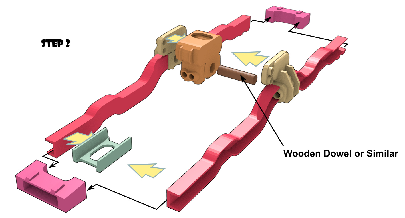
Step 2
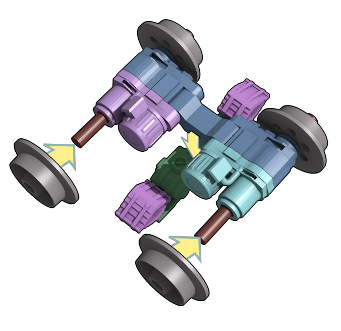
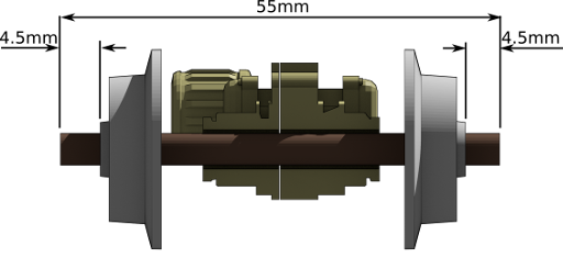
Slide the wheels onto the Ø4mm 54mm long dowels, and allow sufficient to stick out where it can engage with the recesses on the side panels. This is typically 4.5mm each side.
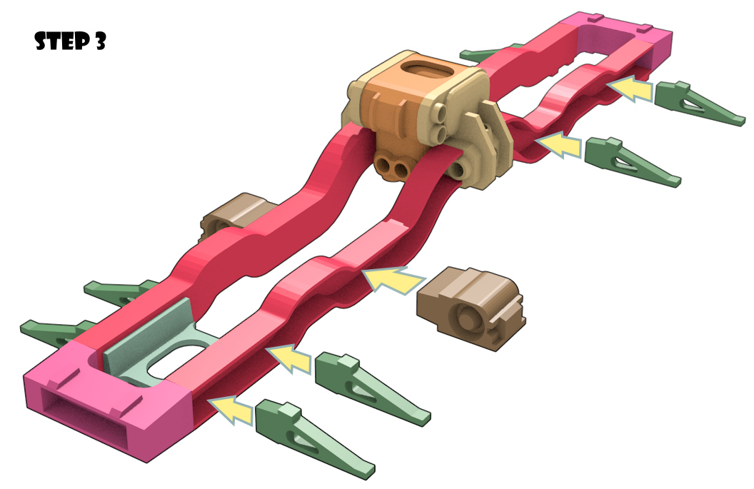
Step 3
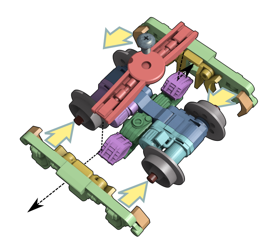
Drop the upper cross piece down onto the leaf springs and slide the side pieces into place.
Completed Assembly
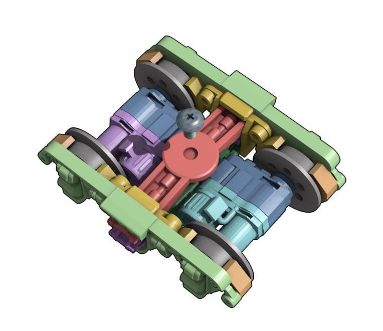
This is just to illustrate how the assembled bogie should look.
And now, do it all again on the second set.
Assembling the Deck
On a good flat surface glue the side rails onto the Undermass Left and Right components. Just be aware which way the wobbles go and where the two lugs on the back of the “UnderbarsBack” components are. It will pay to use a straight edge along what will be the top surface of the “Underbars” to ensure the deck is glued straight.
Use the small Ø4mm dowel stub to help locate the two side sections. Glue the endcaps and FrontWeb in place.
Add the footplate supports and the two battery tray terminal blocks. To make things easy, lay the assembly on its back as shown and pack up the footplate supports with some cardboard so they are sitting flat.

Add the batteries to the battery tray making sure you have the battery terminals around the right way. It may pay to clear the recesses in the battery terminals at this stage which you still have easy access with a drill. Put the “Charge Controller” component in place with the larger flat top surface flush with the top of the assembly. Add the footplates. Glue the “Generator” section to the Back Hub cap. Add the back tray too.
Before gluing on the battery tray and the front and back hubcap assemblies, check the fit with your motorbike model. You will probably need to slide the battery tray around a bit to get it to fit depending on the type of model you are using. When you are satisfied with the fit, glue them in place.
Assemble the two buffers. Use the deck assembly to ensure the spacing between the webs is correct.
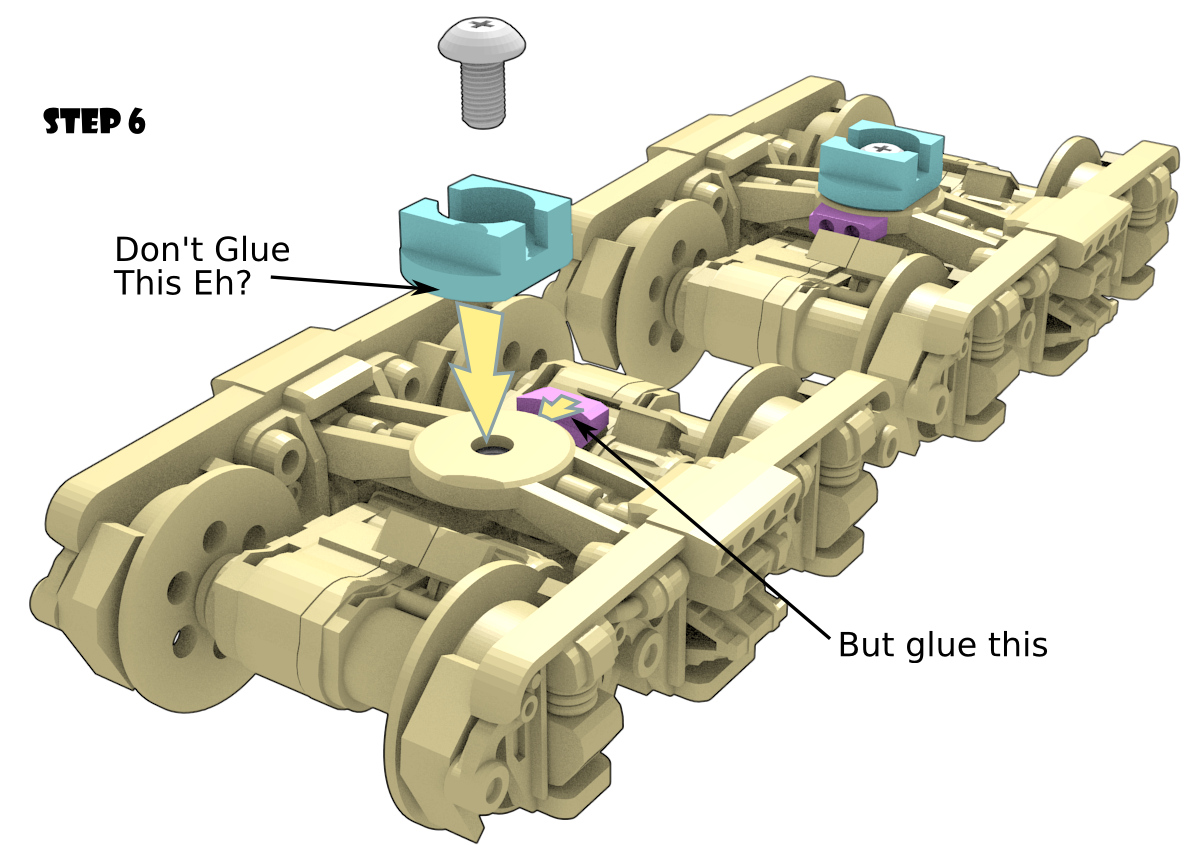
Grab your two finished bogies and add the two bogie wire terminals. These are where your wires will connect. The two bogie hubs can be installed. These are not glued. Leave a little looseness in the screws so the bogie pivot will turn. It is probably worth adding a washer in between the bogie and the bogie hub to allow smooth rotation.
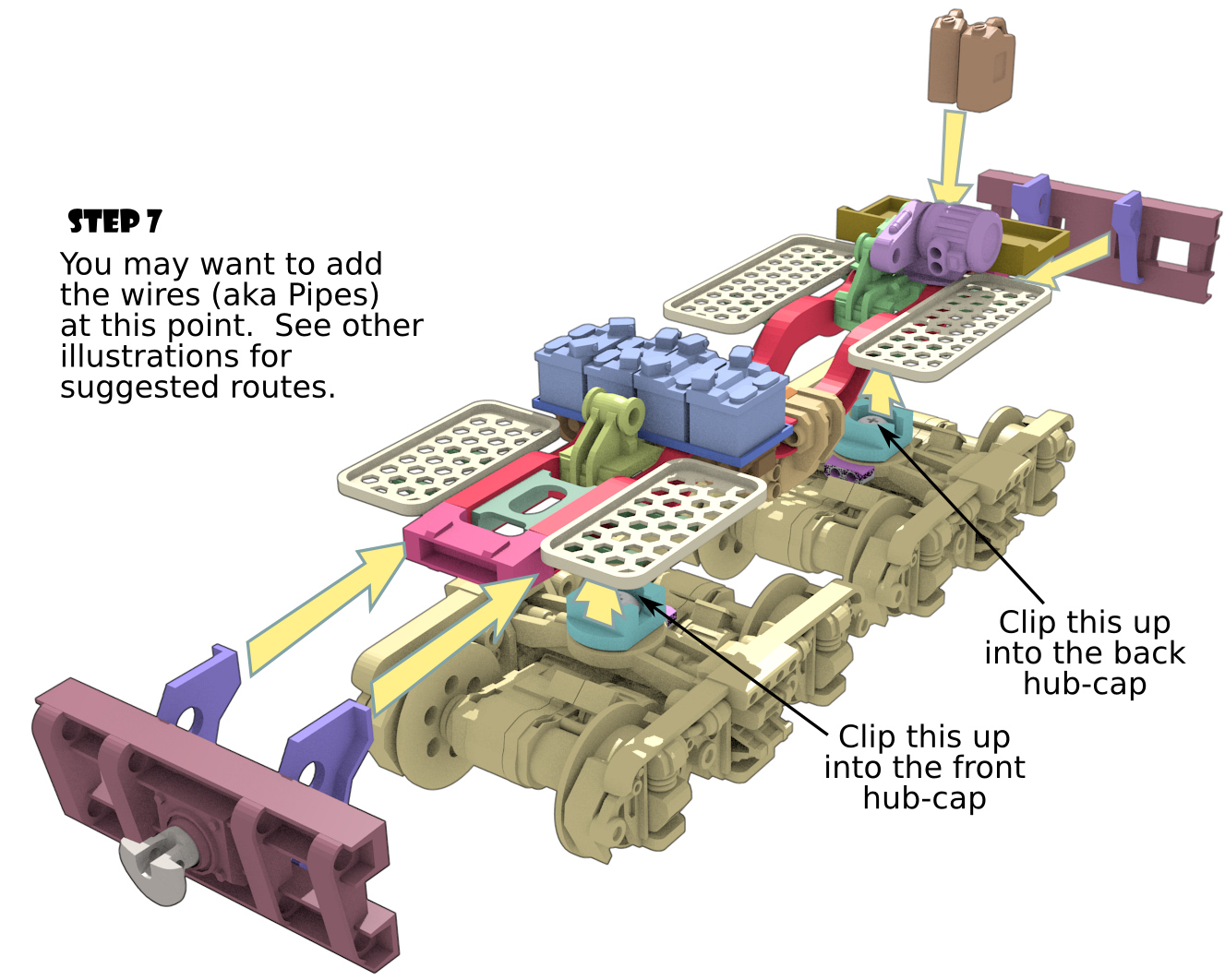
The bogies should clip up into the front and back hubcaps which are now mounted in the deck assembly. There is no need to glue this in place.
With the bogies installed and the assembly sitting on rails or at least something that will allow it to sit as it would on rails, glue the buffers in place allowing space below them so they’re not dragging on the ground. Don’t slide them too close to the bogies either, you still want the bogies to be able to swivel a bit.
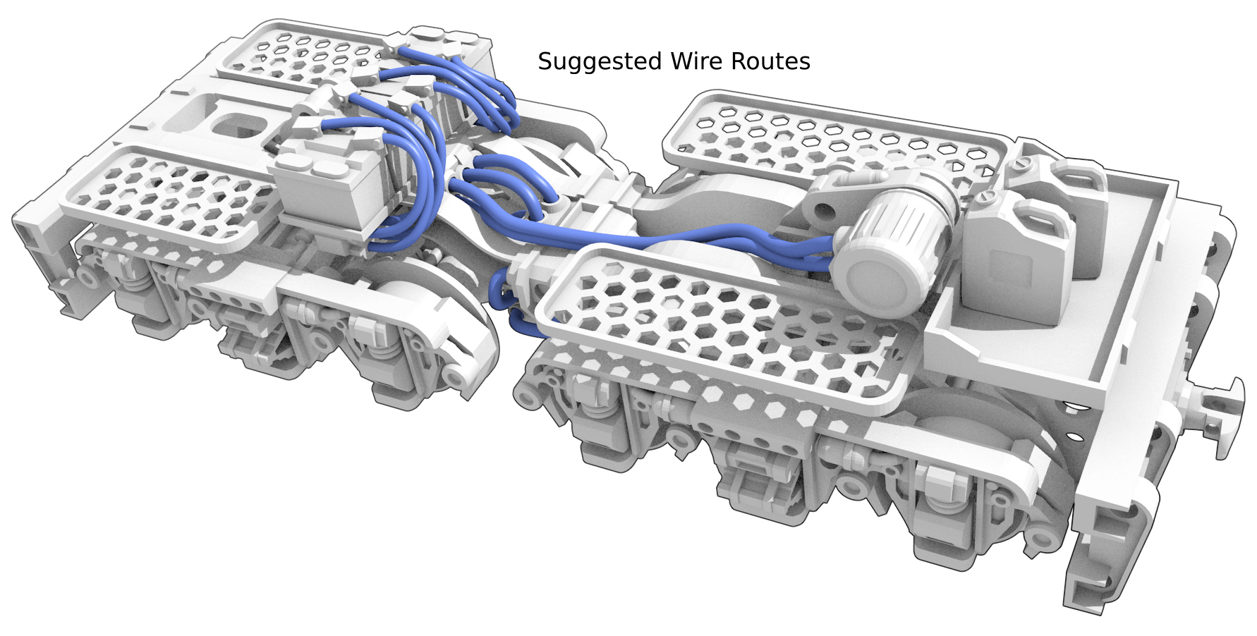
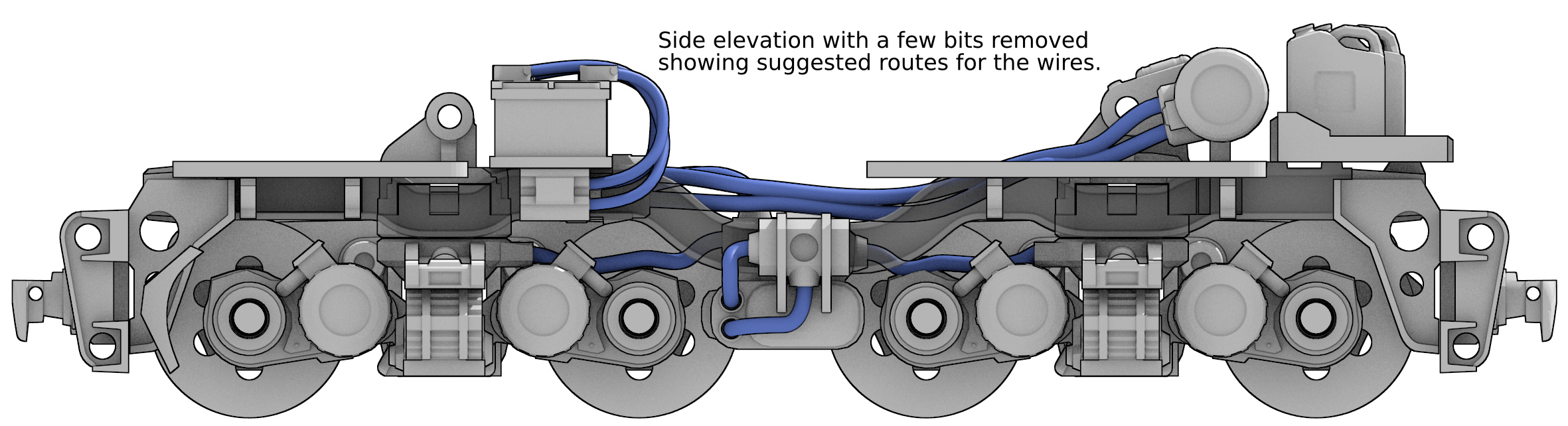
Add the wires to simulate the cable routes. Below are the routes I used on mine.
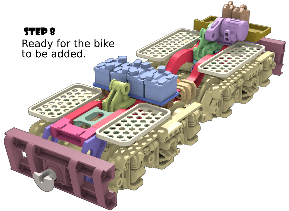
Now you have the wires in place, and the bogies clipped in, the assembly is ready for the bike. I used a couple of stubs of old nail to clip the bike in place. The fit was tight enough that I did not bother gluing it. This means the bike’s suspension works too.
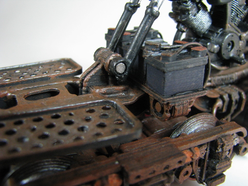
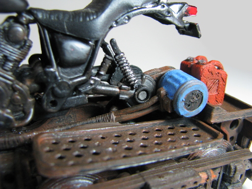
Here are some detailed photos of the bike’s connection to the 3d printed assembly.
If you are looking for tracks to display it on, then have a look at these parametric track models. You will just need to set the track gauge to 36mm and sleeper length to 58mm to be compatible with this model.
And that’s it. Other details such as canvas roles, sachels and the like I will add, but these will be made from oven baked modelling clay or rolled up tissue and PVA.
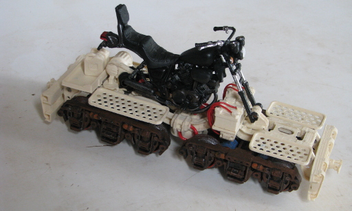
Some Pretty Pictures
Ready for Final Assembly
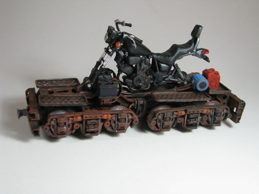
Trial Assembly
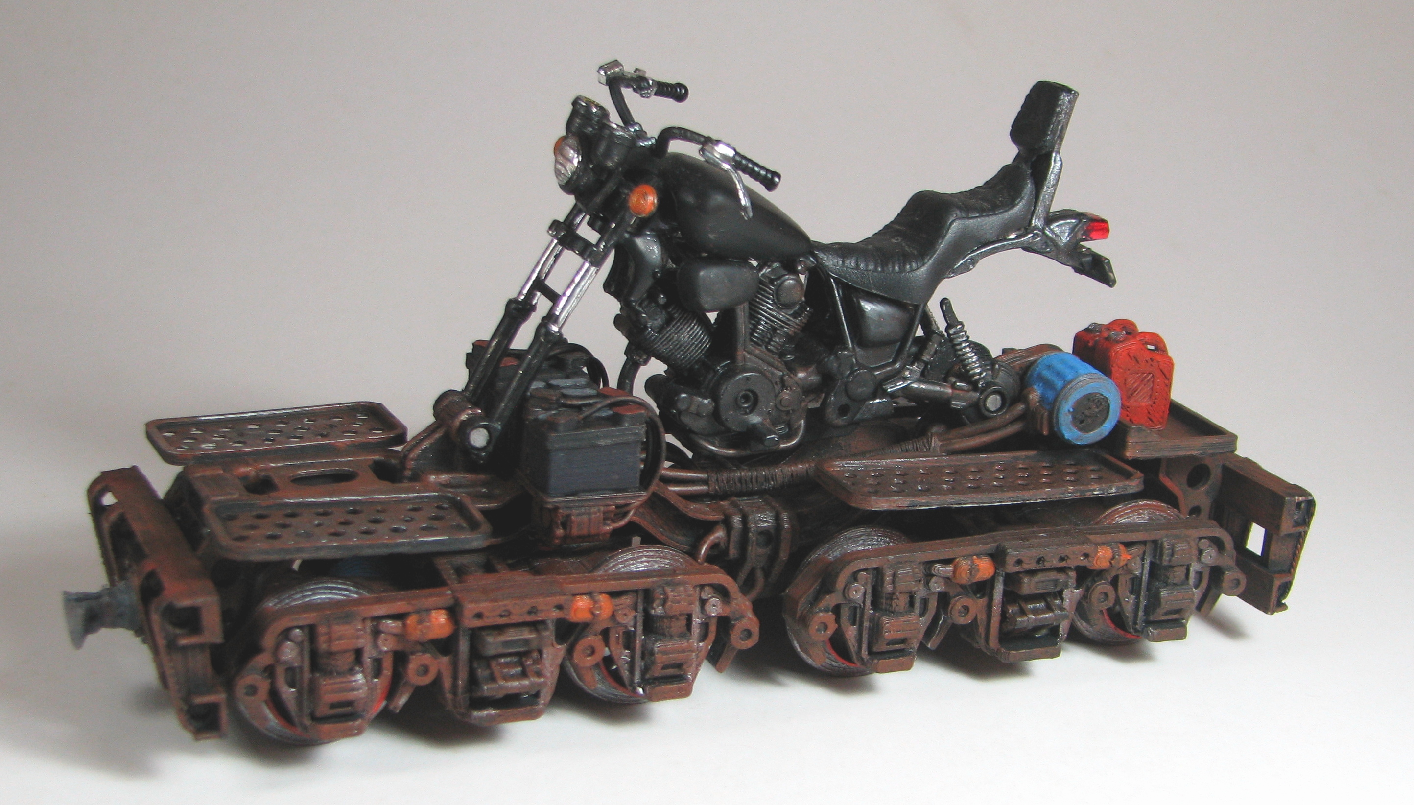
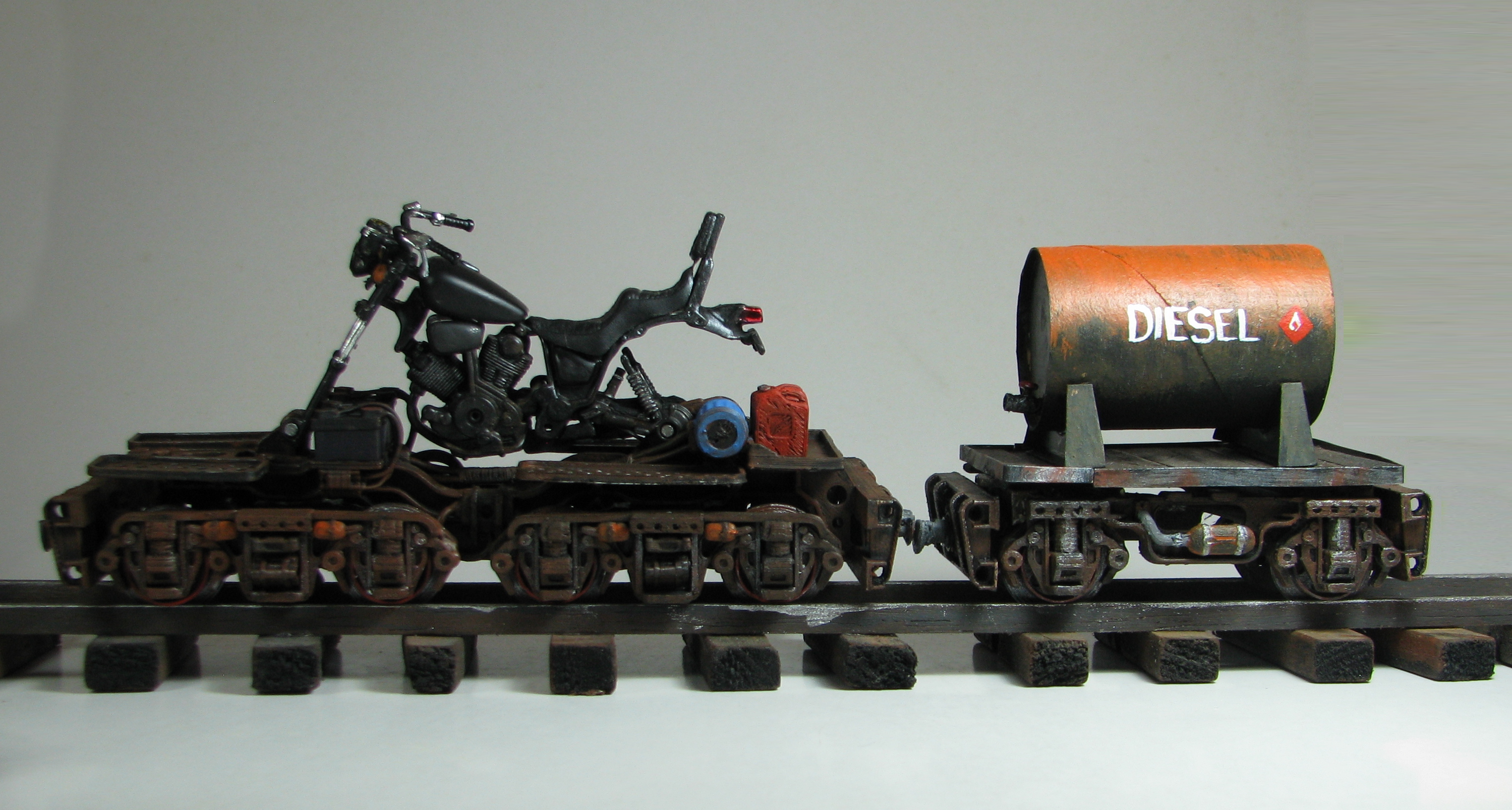
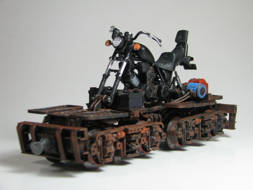
Finished


This design by Hamish Trolove is licensed under a Creative Commons Attribution-NonCommercial-ShareAlike 4.0 International License.