Using the MX1508 Brushed DC Motor Driver with an Arduino

I have a few low voltage brushed motors that I have been meaning to make use of in a couple of projects. I was keen to try out one of the Brushed DC Motor Control boards sold by Banggood. I found this one;
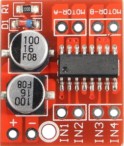
listed as a “Dual Channel L298N DC Motor Driver Board PWM Speed Dual H Bridge Stepper Module”. When it arrived and I looked at the writing on the chip I could see that it wasn’t an L298 chip, but rather an MX1508 – not that this was a problem.
This board can drive two motors independently. It incorporates an H-bridge for each motor and so can drive the motors in either direction. It is rated at 1.5A on each motor with a peak of 2.5A. The motors I wanted to test drew 0.5A when working hard. In can be used with low voltage motors (voltages lower than the Arduino pin voltages). The motor speed is controlled with a Pulse Width Modulated (PWM) signal to the IN connections.
There is some discussion on some forums where people describe a few problems with reverse EMF voltage spikes coming back through the system and confusing their micro-controllers. The MX1508 breakout board sold by Banggood appears to have all the necessary capacitors and flyback diode to combat this. I haven’t found any problems despite using it with a particularly dirty Tamiya 70103 gear motor. This same gear motor would frequently cause my Arduino to reset when running it with a single transistor controller arrangement.
Connections
The connections are very simple as you can see in the diagram below. This is the arrangement I used for the Arduino sketches described in this article. Obviously, to drive a second motor you would just connect the board’s IN3 and IN4 connections to two spare PWM enabled pins on the Arduino and connect your second motor to the Motor-B connections. On the Arduino Nano, the PWM pins are; D03, D05, D06, D09, D10, and D11.
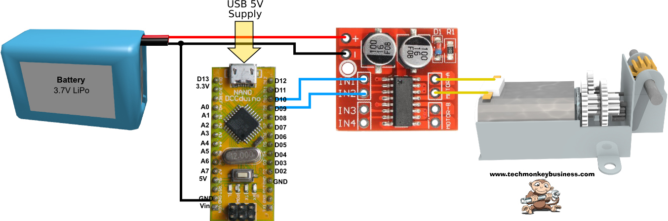
Click on the image for a hi-res version.
Simple Example
This sketch repeatedly runs the motor at a constant speed (MaxSpd) in one direction for a period (ActTime) then runs in the reverse direction for the same length of time. There is a slight pause between the two runs to minimise the chance of large reverse EMF spikes being generated by slamming the motor into reverse. You can download this sketch from here: MX1508_ControllerSimplev0.ino
//MX1508_ControllerSimplev0.ino

/*
This is a quick Demo sketch for control of a low voltage
brushed DC motor using the MX1508 breakout board.

We will only control one motor but drive it forward and reverse.
To keep it simple(ish), no input from the user is used.

Motor maximum voltage is 3V

Pin connections (Arduino Nano):
D9  To Motor Controller Port IN2
D10 To Motor Controller Port IN1
*/

const int FwdPin = 10; //Forward Motor Pin
const int BwdPin = 9;  //Backward Motor Pin

long ActTime = 3000; // The time for a particular part of the cycle.

int MaxSpd = 180; //Top speed (0-255)

boolean DirFlag = true; //Flag for direction

void setup()
{
  pinMode(FwdPin, OUTPUT);
  pinMode(BwdPin, OUTPUT);
}

void loop()
{
  if(DirFlag)
  {
    analogWrite(FwdPin,MaxSpd);  //Send instructions to Forward motor pin
    delay(ActTime);
    analogWrite(FwdPin,0);
    DirFlag =! DirFlag; //Toggle Direction flag
    delay(20);
  }
  else
  {
    analogWrite(BwdPin,MaxSpd);  //Send instructions to Backward motor pin
    delay(ActTime);
    analogWrite(BwdPin,0);
    DirFlag =! DirFlag; //Toggle Direction flag
    delay(20);
  }
}
Timer controlled motion with speed ramps
This was a slightly more complex sketch to make use of timers rather than delays and also ramp the speeds up and down. MaxSpd controls the top speed while ActTime controls the length of time ramping up, running at a constant speed and decelerating. Small delays are sprinkled through the sketch to allow time for some events to happen. I found if I left them out the Arduino would sometimes trip over itself. You can download this sketch from here: MX1508_Controllerv1.ino
//MX1508_Controllerv1.ino

/*
This is a quick Demo sketch for control of a low voltage
brushed DC motor using the MX1508 breakout board.

We will only control one motor but drive it forward and reverse.
To keep it simple(ish), no input from the user is used.
To make it more complex, we'll control it with timers.  This allows
all sorts of other processes to be added in parallel without
delays mucking it up.

Times at the different speeds and ramp times will all be 3 seconds
long.

Motor maximum voltage is 3V

Pin connections (Arduino Nano):
D9  To Motor Controller Port IN2
D10 To Motor Controller Port IN1
 */

const int FwdPin = 10;
const int BwdPin = 9;

int CurSpd = 0; //Current Speed
long ActTime = 3000; // The time for a particular part of the
                      //cycle.

long RunStrtTime = 0; //This keeps track of the time the motion begins

int MaxSpd = 180; //Top speed (0-255)

boolean DirFlag = true; //Flag for direction

void setup()
{
  pinMode(FwdPin, OUTPUT);
  pinMode(BwdPin, OUTPUT);

  delay(5000);  //My customary 5 second delay to allow an uploading window

  RunStrtTime = millis(); //Reset the start time
}

void loop()
{
  //Control the process with timers rather than use delays.

  //To control the Motion we will use a bunch of If and Else if
  //Statements to keep track of which stage the motion is in.

  if (millis() - RunStrtTime > 0 && millis() - RunStrtTime <= ActTime)
  {
    //Time to start accelerating the Motor
    //Find the appropriate current speed by interpolating
    CurSpd = MaxSpd * float(millis() - RunStrtTime) / float(ActTime);
  }

  else if (millis() - RunStrtTime > ActTime && millis() - RunStrtTime <= 2 * ActTime)
  {
    CurSpd = MaxSpd;  //Set current speed to Maximum Speed
  }

  else if (millis() - RunStrtTime > 2 * ActTime && millis() - RunStrtTime <= 3 * ActTime)
  {
    //Time to decelerate the Motor
    //Find the appropriate current speed by interpolating
    CurSpd = MaxSpd - MaxSpd * float(millis() - RunStrtTime - 2 * ActTime) / float(ActTime);
  }

  else if (millis() - RunStrtTime > 3 * ActTime )
  {
    //Motion complete set speed to zero.
    CurSpd = 0;  //Set current speed to 0
    RunStrtTime = millis(); //Reset the start time
    analogWrite(FwdPin,int(CurSpd));
    analogWrite(BwdPin,int(CurSpd));
    delay(1000);
    DirFlag =! DirFlag;  //Toggle the direction flag
    delay(5);
  }

  //Set the motors going with the current speed

  delay(5); //just to give things a little time to stabilise and do their thing
  if(DirFlag)
  {
    analogWrite(FwdPin,int(CurSpd));  //Send instructions to Forward motor pin
  }
  else
  {
    analogWrite(BwdPin,int(CurSpd));  //Send instructions to Backward motor
  }
  delay(5);
}
Hopefully this will be useful for you. If you are after a single transistor DC motor controller circuit and sketch, please check out this article: DC Motor Motion Sequence Controller

Note:
This article and associated coding by Hamish Trolove are licensed under a Creative Commons Attribution-ShareAlike 4.0 International License.