DC Motor Motion Sequence Controller

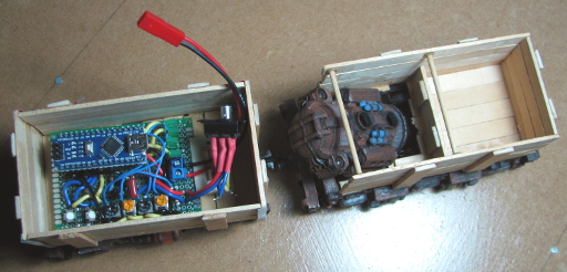
This article describes a relatively simple motion controller for a small DC Motor. It was designed for a Go-Motion Mine Trolley based on my 3D printed stop-motion mine trolley model. The circuit makes use of an Arduino and its pulse width modulated (PWM) signal output to control the motor speed through a transistor. I was purposefully trying to keep it simple and not use a purpose-made DC motor controller breakout board - mainly because I didn’t have one at the time. Since trying out the MX1508 Brushed Motor Controller I feel using that would have yielded a slightly more compact controller with the added ability to reverse the motor direction.
So what I came up with was a motor controller with the following features;
- Used an Arduino Nano to be the brains,
- had a separate START and STOP button,
- used a potentiometer select one of the preloaded motion timing sequences to run,
- had a set of LEDs to indicate which timing sequence was being used,
- used 3 potentiometers to dial up the speeds at the different stages in the sequence,
- used a switch to control the motor direction,
- used a 12V geared motor,
- and ran off an 11V LiPo battery.
I did not want to use any screens for the user interface for the simple reason that I didn’t have a huge amount of space to work with and I wanted to be able to darken the system as much as possible while it was running. This latter point was to avoid light seeping out from the controller and spoiling the shot.
The choice of potentiometers for the user input had three major benefits; no input “bounce” as would be experienced with push buttons, no need for a sophisticated display for feedback while changing settings, and the settings would remain as the user last left them. It also meant that speed settings could be changed while the trolley was in motion if there was a need to select an exact speed.
The Hardware
The diagram on the next page shows the circuit for this system.
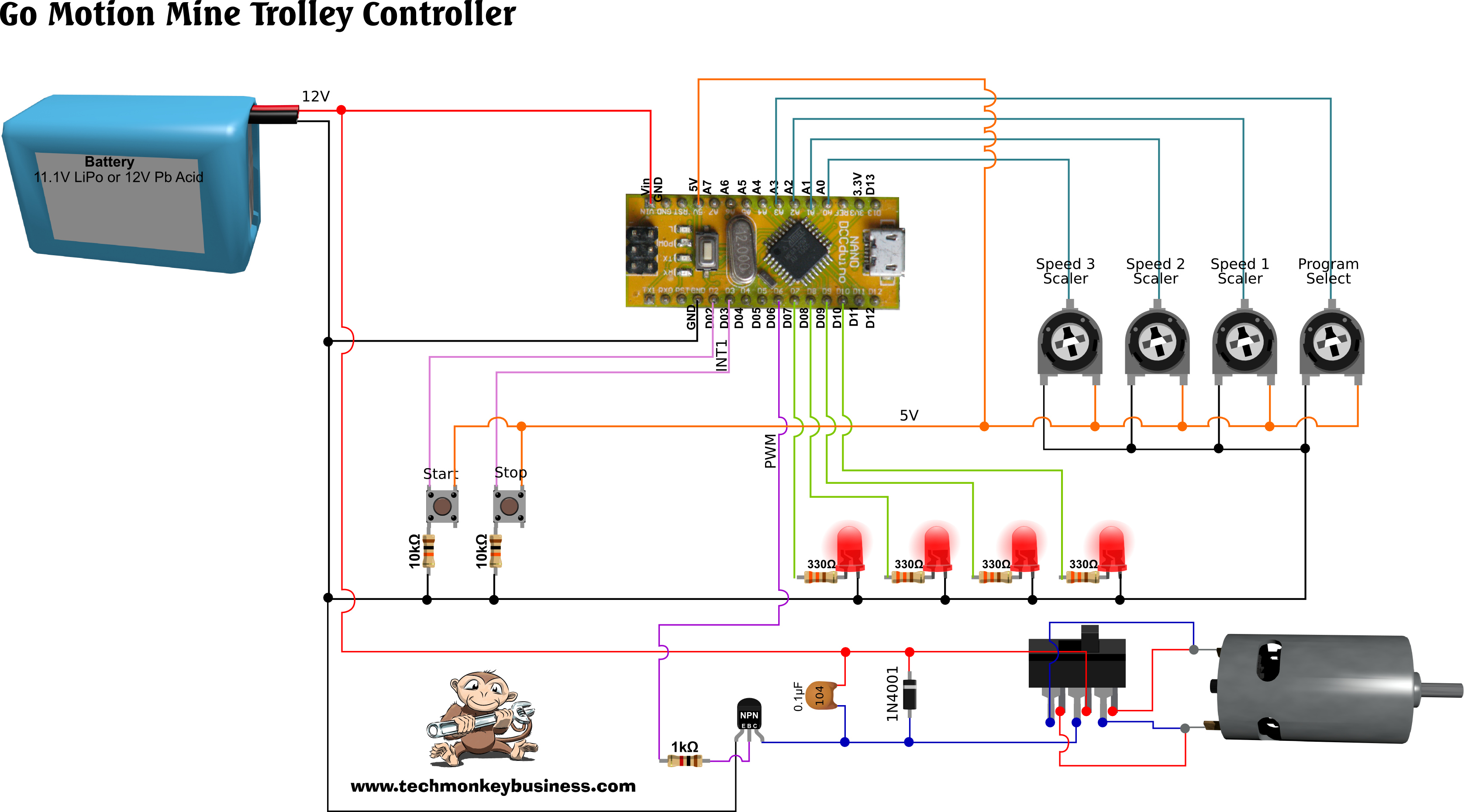
Click on the image for a higher resolution image.
On perfboard the layout becomes.
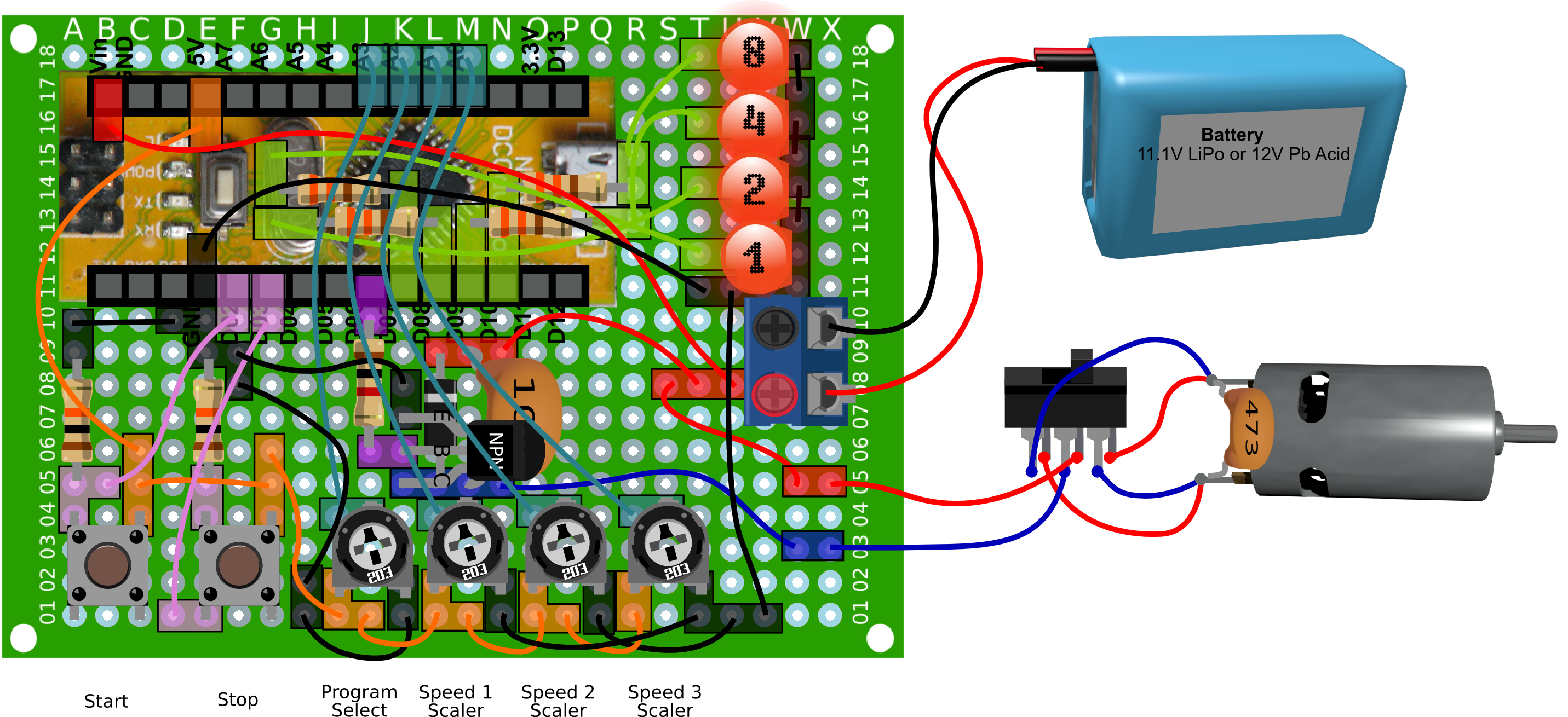
Click on the image for a higher resolution image.
The Arduino is plugged into a pair of headers so it can be removed. This allows some of the resistors and wiring to be run underneath the Arduino. Unfortunately this makes the diagram a little confusing. The four 330Ω resistors for the LEDs are installed under the Arduino, and the 5V wire (orange) to the buttons, the 11.1V supply wire (red) and the ground wire (black) all run through, and connect to the board, in the space under the Arduino.
Speed Control
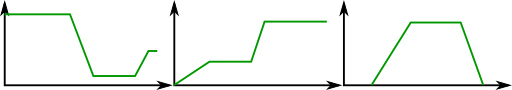
The motion controller is programmed to run the motor through a sequence of three speeds. The speeds at each stage are selected using the three motor speed potentiometers. This allows the user to create a speed profile that looks something like this.
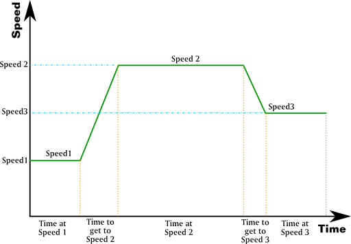
But because the user can dial the speeds all the way to zero, there are a large number of different types of speed profiles that can be achieved without changing the hardware or the Arduino code.
Program Selection
In the interests of reducing the wear and tear on the USB connection and the flash memory, I decided to have a selection of sixteen timing programs build into the Arduino Code. The user would then use the Program Selector potentiometer to choose the timing program that best suited their needs.
The 16 programs in the Arduino sketch presented here are;
|
Program ID |
Binary ID |
Time at Speed 1 |
Time to Speed 2 |
Time at Speed 2 |
Time to Speed3 |
Time at Speed 3 |
|
0 |
0000 |
1 |
4 |
10 |
4 |
10 |
|
1 |
0001 |
3 |
4 |
10 |
4 |
10 |
|
2 |
0010 |
6 |
8 |
10 |
8 |
10 |
|
3 |
0011 |
10 |
8 |
10 |
8 |
10 |
|
4 |
0100 |
1 |
8 |
10 |
8 |
6 |
|
5 |
0101 |
3 |
8 |
6 |
8 |
8 |
|
6 |
0110 |
6 |
4 |
5 |
4 |
4 |
|
7 |
0111 |
10 |
4 |
2 |
4 |
10 |
|
8 |
1000 |
1 |
3 |
12 |
6 |
10 |
|
9 |
1001 |
3 |
3 |
15 |
6 |
4 |
|
10 |
1010 |
6 |
4 |
12 |
6 |
6 |
|
11 |
1011 |
10 |
4 |
15 |
6 |
2 |
|
12 |
1100 |
1 |
6 |
6 |
4 |
10 |
|
13 |
1101 |
3 |
6 |
6 |
4 |
14 |
|
14 |
1110 |
6 |
6 |
6 |
2 |
3 |
|
15 |
1111 |
10 |
6 |
6 |
3 |
8 |
The times in the table are in seconds. The sketch has the array called ProgDict[][] which contains this list of programs. As presented here, ProgDict is an integer variable and so if you are after fractions of a second, you will need to change this to a float variable.
The Binary ID column is the program number expressed as a binary number. This is what will be seen on the four LEDs. As the program selection potentiometer is changed so the LEDs will change to reflect a different binary number corresponding to a particular timing program being selected.
The Sketch
Finally, here is the sketch. You can download it from here; GoMotionTrolleyControlv4.ino
Use of delays has been minimised (other than where needed to prevent it tripping over itself in it haste) to ensure the smooth operation of the sketch. Hopefully the comments through the code will help make sense of it.
//GoMotionTrolleyControlv4.ino
/*
  This is a sketch to control a small DC motor driving a
  3DPrinted Mine Trolley.  There is a selection of
  preset runtimes to use so as to avoid taking up extra space
  with screens and such.

  We will use separate buttons to start and stop the run
  so as to get around debouncing problems.  A potentiometer
  is used to select the motion programme.  This will allow
  the setting to persist between sessions.

  A series of potentiometers are used to scale the different speeds.

  Pin assignments

  Pin D6 PWM control of the transistor
  Pin D2 Button for starting chosen programme (on interrupt pin 0)
  Pin D3 Halt run (on interrupt pin 1)
  Pin A3 Potentiometer Sweeper to Cycle Program Down and Down

  Pin A2 Potentiometer Sweeper to scale Spd1
  Pin A1 Potentiometer Sweeper to scale Spd2
  Pin A0 Potentiometer Sweeper to scale Spd3

  Pin D7 Program Indicator LED
  Pin D8 Program Indicator LED
  Pin D9 Program Indicator LED
  Pin D10 Program Indicator LED


*/

int ProgNo = 0;  //The ID for the particular programme
//being run

int Spd1 = 0; //Starting Speed (0-255)
int Spd2 = 0;  //Second Speed (0-255)
int Spd3 = 0;  //Third Speed (0-255)
long Spd1Time = 0; //Time at Spd1 (ms)
long Spd2Time = 0; //Time at Spd2 (ms)
long Spd3Time = 0; //Time at Spd3 (ms)
long S1S2Time = 0;  //Time to go from Spd1 to Spd2 (ms)
long S2S3Time = 0;  //Time to go from Spd2 to Spd3 (ms)

long CurSpd = 0; //Current Speed  (0-255)

boolean RunFlag = 0; //Flag for running the programme
boolean LEDBlinkState = false; //Flag for controlling the LED blinks

const int MotorPin = 6;  //The Motor Pin
const int StartRun = 2; //Pin D2 Button for starting chosen programme
const int StopRun = 3;  //Pin D3 to stop the run (interrupt INT1)
const int ProgUP = A3;  //Analogue Pin A3 Cycle Program Up and Down

const int Spd1Pot = A2;  //Analogue Pin A2 to change Spd1
const int Spd2Pot = A1;  //Analogue Pin A1 to change Spd2
const int Spd3Pot = A0;  //Analogue Pin A0 to change Spd3

const int NoxLEDs = 4;  //Number of LEDs
const int ProgBinLED[] = {7, 8, 9, 10}; //ProgramID indicator LEDs

long RunStrtTime = 0; //This keeps track of the time the motion
//Programme begins.
long BlinkPing = 0; //This is a timer holder for controlling
// The delay-less blink.

// Program Array content: Time at starting speed,
// Time to second, hold time at second speed, time to third speed,
// hold time at third speed

int ProgDict[][5] = {
  {1, 4, 10, 4, 10},
  {3, 4, 10, 4, 10},
  {6, 8, 10, 8, 10},
  {10, 8, 10, 8, 10},
  {1, 8, 10, 8, 6},
  {3, 8, 6, 8, 8},
  {6, 4, 5, 4, 4},
  {10, 4, 2, 4, 10},
  {1, 3, 12, 6, 10},
  {3, 3, 15, 6, 4},
  {6, 4, 12, 6, 6},
  {10, 4, 15, 6, 2},
  {1, 6, 6, 4, 10},
  {3, 6, 6, 4, 14},
  {6, 6, 6, 2, 3},
  {10, 6, 6, 3, 8}
};

void setup()
{
  delay(5000);  //Five seconds delay to allow other processes such
  //as new uploads to get a chance to happen

  pinMode(MotorPin, OUTPUT);
  pinMode(StartRun, INPUT);
  pinMode(StopRun, INPUT);
  pinMode(ProgUP, INPUT);
  pinMode(Spd1Pot, INPUT);
  pinMode(Spd2Pot, INPUT);
  pinMode(Spd3Pot, INPUT);

  attachInterrupt(1, SwitchRun, RISING); //Interrupt to halt program

  for (int i = 0; i < NoxLEDs; i++)
  {
    pinMode(ProgBinLED[i], OUTPUT);
    digitalWrite(ProgBinLED[i], LOW);  //Set all LEDs to off.
  }

}

void loop()
{

  //When the program is not running we can adjust which program
  //we want to use.

  while (RunFlag == false)
  {
    //Read the potentiometer state and select the program
    analogWrite(MotorPin, 0); //Stop the motor
    ProgNo = map(analogRead(ProgUP), 0, 1023, 0, 15);

    //Based on the selected Programme, load the appropriate
    //times and times between different speeds
    Spd1Time = 1000 * ProgDict[ProgNo][0];
    S1S2Time = 1000 * ProgDict[ProgNo][1];
    Spd2Time = 1000 * ProgDict[ProgNo][2];
    S2S3Time = 1000 * ProgDict[ProgNo][3];
    Spd3Time = 1000 * ProgDict[ProgNo][4];

    //Match the selected program with the appropriate LED
    //Sequence ( taken from https://gist.github.com/adamatan/3188066)

    BinNumberLEDs(ProgNo);  //Send the ProgrammeID number to the function

    //To stop this loop, look for the start run button being pressed
    if (digitalRead(StartRun) == HIGH)
    {
      RunFlag = true;
      RunStrtTime = millis(); //Store the time the run is started.
    }
  }

  while (RunFlag == true)
  {
    //Control the process with timers rather than use delays.

    //Read the potentiometers to determine the speeds
    Spd1 = map(analogRead(Spd1Pot), 0, 1023, 0, 255);
    Spd2 = map(analogRead(Spd2Pot), 0, 1023, 0, 255);
    Spd3 = map(analogRead(Spd3Pot), 0, 1023, 0, 255);

    //Have a five second wait before action starts to allow
    //the user to get their hands out of the way and back
    //to their camera.

    while (millis() - RunStrtTime < 5000)
    {
      Delaylessblink();
      delay(5); //just to stop it tripping over itself
    }

    //Have one more second to turn off all LEDs and prepare to move
    if (millis() - RunStrtTime > 5000 && millis() - RunStrtTime < 6000)
    {
      //Turn all LEDs off to prevent their light spoiling shooting.
      for (int i = 0; i < 4; i++)
      {
        digitalWrite(ProgBinLED[i], LOW);
      }
      delay(5); //just to stop it tripping over itself
    }

    //To control the Motion we will use a bunch of If and Else if
    //Statements to keep track of which stage the motion is in.

    else if (millis() - RunStrtTime - 6000 > 0 && millis() - RunStrtTime - 6000 < Spd1Time)
    {
      //We're in the first stage and running a Sp1 for a period
      CurSpd = Spd1;  //Set current speed to Spd1
    }

    else if (millis() - RunStrtTime - 6000 > Spd1Time && millis() - RunStrtTime - 6000 < Spd1Time + S1S2Time)
    {
      //Time to start accelerating the Trolley
      //Find the appropriate current speed by interpolating
      CurSpd = Spd1 + (Spd2 - Spd1) * float((millis() - RunStrtTime - 6000 - Spd1Time)) / float(S1S2Time);
    }

    else if (millis() - RunStrtTime - 6000 > Spd1Time + S1S2Time && millis() - RunStrtTime - 6000 < Spd1Time + S1S2Time + Spd2Time)
    {
      CurSpd = Spd2;  //Set current speed to Spd2
    }

    else if (millis() - RunStrtTime - 6000 > Spd1Time + S1S2Time + Spd2Time && millis() - RunStrtTime - 6000 < Spd1Time + S1S2Time + Spd2Time + S2S3Time)
    {
      //Time to accelerate the Trolley from Spd 2 to Spd3
      //Find the appropriate current speed by interpolating
      CurSpd = Spd2 + (Spd3 - Spd2) * float((millis() - RunStrtTime - 6000 - Spd1Time - S1S2Time - Spd2Time)) / float(S2S3Time);
    }

    else if (millis() - RunStrtTime - 6000 > Spd1Time + S1S2Time + Spd2Time + S2S3Time && millis() - RunStrtTime - 6000 < Spd1Time + S1S2Time + Spd2Time + S2S3Time + Spd3Time)
    {
      //Stage three speed.
      CurSpd = Spd3;  //Set current speed to Spd3

    }

    else if (millis() - RunStrtTime - 6000 > Spd1Time + S1S2Time + Spd2Time + S2S3Time + Spd3Time)
    {
      //Motion complete set speed to zero.
      CurSpd = 0;  //Set current speed to 0
      RunFlag = false;
    }

    delay(5); //just to give things a little time to stabilise and do their thing
    analogWrite(MotorPin, int(CurSpd)); //Write the current speed to motor control pin
    delay(5);
  }
}


void BinNumberLEDs(int num)  // https://gist.github.com/adamatan/3188066
{
  for (int i = 0; i < 4; i++)
  {
    if (num % 2)
      digitalWrite(ProgBinLED[i], HIGH);
    else
      digitalWrite(ProgBinLED[i], LOW);
    num /= 2;
  }
}

void SwitchRun()  //Interrupt handler function
{
  RunFlag = false;
}


void Delaylessblink()
{
  if (millis() - BlinkPing > 500)
  {
    BlinkPing = millis();  //Update the stored time
    //Toggle the state of the LEDs on all pins
    LEDBlinkState = !LEDBlinkState;
    digitalWrite(ProgBinLED[0], LEDBlinkState);
    digitalWrite(ProgBinLED[1], !LEDBlinkState);
    digitalWrite(ProgBinLED[2], LEDBlinkState);
    digitalWrite(ProgBinLED[3], !LEDBlinkState);
  }
}

Note:
This article and associated coding by Hamish Trolove are licensed under a Creative Commons Attribution-ShareAlike 4.0 International License.