Quadcopter V2 - Quadcopterus Robusticus
Description
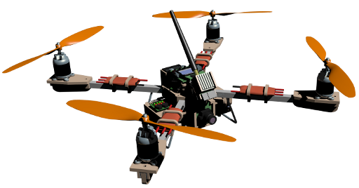
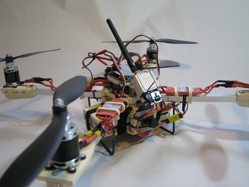
This is an update of my first crack at a Quadcopter. It may not be as pretty as the first one but it is somewhat more robust than the previous one. It is designed to be used as an FPV platform and has moderate extra carrying capacity. The project was originally posted on Thingiverse.
Project Updates
(Note - Aug 2015) More recently, I have replaced the KK2 board with a CC3D controller that I purchased from DX. The quadcopter now flies much more reliably. I finally figured out that it wasn’t that my piloting was crap, but it was the KK2 board telling one of the motors to take a rest at random times that was causing the quadcopter to plummet out of the sky.
(Note - Nov 2015) Damn thing! I thought I had eliminated the drop-out problems by replacing the KK2 board. Well it returned with a vengance and did some severe damage to the craft as well as putting a good ding in the Video Transmitter. OK, I think it is time to right this one off and free up the kit for the other purposes. I feel the problem might be in the ESCs thermal cutout in a similar manner as is happening in the ROV. This is a little suprising seeing as the ESCs are not working all that hard. A solution might be slightly higher rated ESCs but to be honest I might just call it quits on this one.
Instructions
This is an updated version of my original Quadcopter. The page for the first design has a few notes about the origin of the project and a few construction notes. The following is a list of the changes made for this new design.
Landing Skids
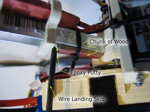
I found that the printed landing skids at the ends of the spars were very vulnerable to breaking even with very light landings, so I have dispensed with this and used a 3.25mm diameter music wire arrangement which is both stronger and adds protection to the battery. You will need to heat the music wire where you are intending to bend it otherwise it will just snap. The wire landing skids fit into the aluminium channel section and are locked in place with a small piece of wood, epoxy putty, and a cable tie. The photo below illustrates this. It’s not pretty but it works.
Battery Holder
The battery holder has also been modified to better locate the battery. I found that the velcro ties were inadequate for holding the battery firmly enough to stop it from slopping around and destabilising the aircraft. There are locations on the battery holder for some light fittings which I have yet to design. Different colour lights for front and back help with working out the aircraft’s orientation if you are not flying FPV.
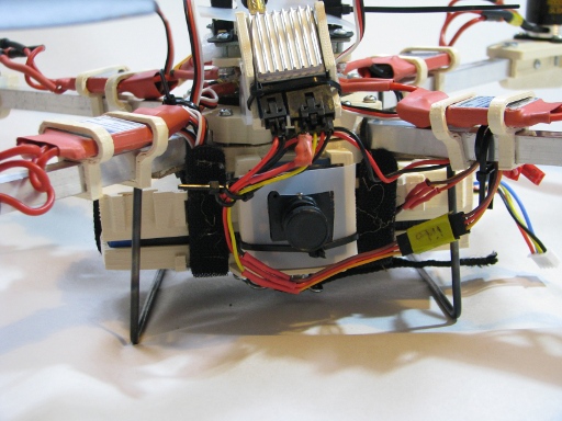
Spar Ends Originally the landing gear was located at the ends of the spars and used to hold the nuts that held down the motor mounts. These have been reduced to just being something to hold the nuts.
Available Files
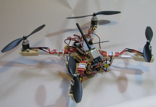
The Blender model is included in the download below to help with assembly or modification. For Non-Blender users there is also a 3DS version in the downloads. STLs have all been tested in Slic3R. Generally I used a 25% fill but the lightly loaded bits such as the feet and top deck were done with a 10% fill. I have included an image and pdf of the small bracket that holds the FPV transmitter on. This is designed to be cut from a piece of plastic bottle and screwed + glued to the back of the printed FPVtransmitter cradle. Bike inner tube rubber and packing foam have been used to back some of the electronic components, and provide soft washers. Plastic tubing has been used to line the top parts of the M4 rods and keep the ESC cables away. Velco ties firmly hold the battery in its cradle, and cable ties have been used extensively to hold components in place and tidy up the wiring. The camera, the receiver and the FPV transmitter are held into their brackets using cable ties.
I recommend clearing out all holes with either a 3.2 or3.5mm drill bit for those designed for the M3 screws or a 4.5mm drill bit for the holes designed to take the four M4 threaded rods. Nylon lock nuts should be used on the M4 rods and the M3 bolts holding the controller onto the top deck. There are quite a few places where recesses have been designed for M3 nuts. These are a snug fit when printed on the Ultimaker but may require clearing with a knife for other printers. The spar ends also have a couple of slots each for M4 nuts. Put the nuts in the slots then clip the spar ends into the aluminium channel to trap them. You will then be able to screw the M4 machine screws into them to hold the whole lot in place. This is illustrated in the Diagrams in the zip-file that can be downloaded with the link above – the diagram has not been updated for this edition of the quadcopter but should still be pretty obvious.
The Power Distribution board supplied by HobbyKing and included in the “Shopping List” file is a really useful piece of kit BUT it’s current rating is not high enough for the currents drawn by the ESCs at full power. I added in some relatively heavy copper wire (powercord cable) between the connectors to carry the additional current. It’s a bit ugly but seems to work.
I thoroughly recommend getting hold of a simulator. Admittedly they are expensive but they are realistic and allow you to develop your automatic skills at flying Radio Control aircraft and ‘copters. The expense is easily offset by saving yourself the time you would otherwise spend repairing and fixing your planes after crashing. I use RealFlight from Towerhobbies, but if you have the right transmitter PhoenixRC is also an excellent simulator. Hobbyking have a simulator based on the open source FMS (Flying Model Simulator) which is not bad and will certainly help but doesn’t quite have the same level of realism as the other two.
I think I am off-topic. Enjoy the project if you make one yourself, and thanks for looking.
Digital Models of the Commercial Components
If you are looking for 1:1 scale digital models of the commercial components used in this project you will be able to find most of them in Blender and OBJ formats on the Component Model Library Page