Parametric Propellers

I have an FPV Shadow RC plane from Banggood that I bought a while ago. The standard kit includes a bunch of 6 inch diameter x 4.5 inch pitch propellers. For a while I would break a prop (and often rip the motor off) each time I landed, because there was nothing to stop the propeller motoring over or being in a vertical position when the plane touched down. I alleviated the problem by adding in two largish coreflute tails that extended below the plane a bit like twin keels on a surfboard. It looks pretty ugly but helps prevent the damage to motor mount and props that I was experiencing. BUT what I felt it really needed was a folding prop. After hunting high and low for quite some time I finally concluded that small 6x4.5 folding props did not exists, and so I decided to see if I could come up with a parametric folding prop that could be 3D printed.
From this development arose two parametric propeller designs; one for a standard fixed propeller with any number of blades, and a variation for folding propellers.
This article describes the OpenSCAD models and how to drive them.
The scripts make use of structures that are only available in OpenSCAD editions after 2015 so grab the latest from www.openscad.org and you will be fine or use the ones on the Thingiverse Customiser.
Multi-Blade Parametric Propeller Model
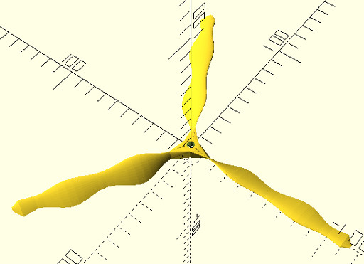
This is a parametric propeller model generator which can create propellers with multiple blades. It was written in OpenSCAD 2015 and uses coding that will not work in older versions. The script makes workable propellers but not necessarily the most beautiful ones. To beauty them up you may want to take the generated model into something like Blender and with a bit of loop bridging make some nicely merging shapes around the hub.
You can find the model on this website here: Multipropv6.scad
or Thingiverse here: www.Thingiverse.com - Thing:3506692
The script (currently) has the NACA4412 airfoil as the blade profile. This produces a very thin blade which is getting into the realm of being a bit too bendy. After a bit of testing I may replace this with a thicker airfoil. If you want to use a different airfoil look for the line;
Airfoil_points = [[1000,1.3],[950,14.7],[900,27.1],[800,48.9],[700,66.9],[600,81.4],[500,91.9],[400,98],[300,97.6],[250,94.1],[200,88],[150,78.9],[100,65.9],[75,57.6],[50,47.3],[25,33.9],[12.5,24.4],[0,0],[12.5,-14.3],[25,-19.5],[50,-24.9],[75,-27.4],[100,-28.6],[150,-28.8],[200,-27.4],[250,-25],[300,-22.6],[400,-18],[500,-14],[600,-10],[700,-6.5],[800,-3.9],[900,-2.2],[950,-1.6],[1000,-1.3]];
… and replace it with your preferred airfoil. The base scale is 1000 units, so you will need to adjust your preferred airfoil to conform with this. I got the points for this airfoil from the airfoil archive, and used the following file: naca4412.dat.
If you are keen to use a different airfoil I have created a Python3 based Airfoil .dat file to OpenSCAD conversion tool. This will produce compatible OpenSCAD files from any .dat file you download from the UIUC Airfoil database. You can find it here: Airfoil .dat to OpenSCAD Conversion Tool
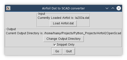
Once you have generated your OpenSCAD style version of the airfoil using this Python script, you can drop the Airfoil_points list directly into these parametric propeller scripts in place of the existing Airfoil_points list currently loaded with the NACA4412 airfoil.
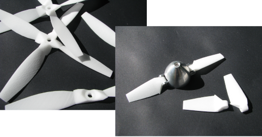
With regard to printing, you may find the trailing edge gets too fine to print so it may be truncated a little. You can see this happening in the photo below where the last 0.5 – 1mm has been lost. I have not tried this on an FDM printer but feel that some sort of support will be required.

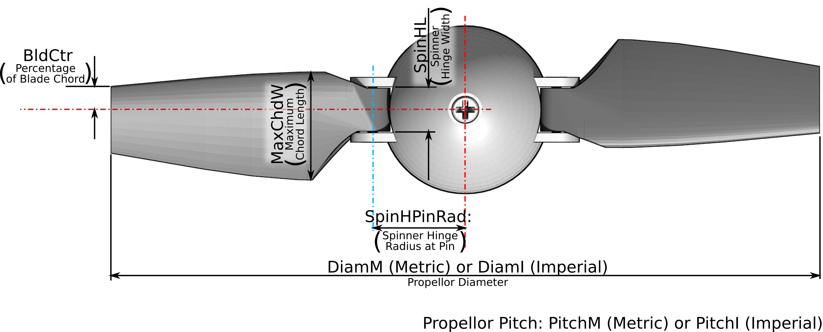
All parameters are millimetres unless otherwise stated. The exception is the blade diameter and pitch which you can fill out with either metric or imperial values. Refer to the diagrams and list below.
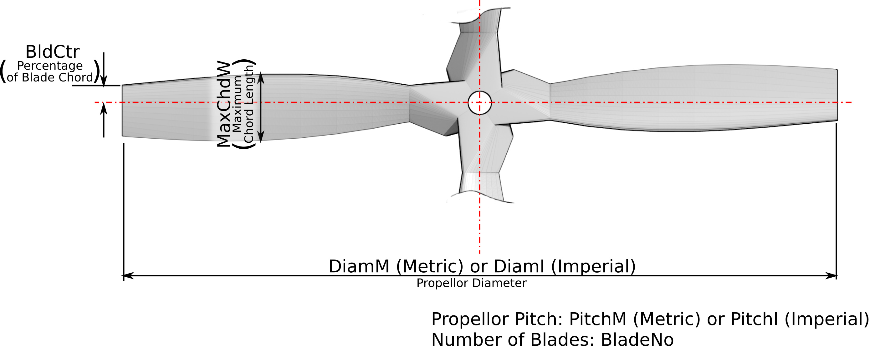
Here is a run down of the parameters used.
The fundamentals
Pitch: Use PitchI for Imperial measurement, or PitchM for metric values.
Diameter: Use DiamI for Imperial measurement, or DiamM for metric values.
Number of blades: BladeNo
Blade Maximum Width (mm): MaxChdW
Calculation Factors
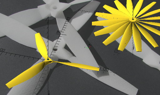
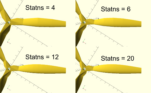
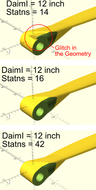
Statns: This is the number of stations along the blade where the size and twist is calculated. A higher number will improve the smoothness of the shape but add to the calculations. See the illustration below for a indication of how different values of Statns look. You may need to fiddle with this when dealing with larger diameter blades to counter the appearance of a gap that sometimes happens.
SectRes: The number of intermediate steps between stations. The higher the number the smoother the shape is but it adds significantly to the calculation time.
Pitch Adjustment
The pitch adjustment was originally introduced to de-rate the pitch angle so that my calculated pitch angles would match what I was measuring from a commercial propeller. As it turns out I must have been measuring the commercial propeller pitch poorly and I should have just run with my unadjusted pitch angles. So, leave these both set to 1.0. It is left here because it may be useful for adding washout to the propeller.
PitchAdjHub: Pitch adjustment factor at the hub end.
PitchAdjTip: Pitch adjustment factor at the hub end.
More Blade and Hub Parameters
BldCtr: This is the position of blade centreline about which the blade is scaled and twisted. It is expressed as a % of the distance along the blade chord measured from the leading edge.
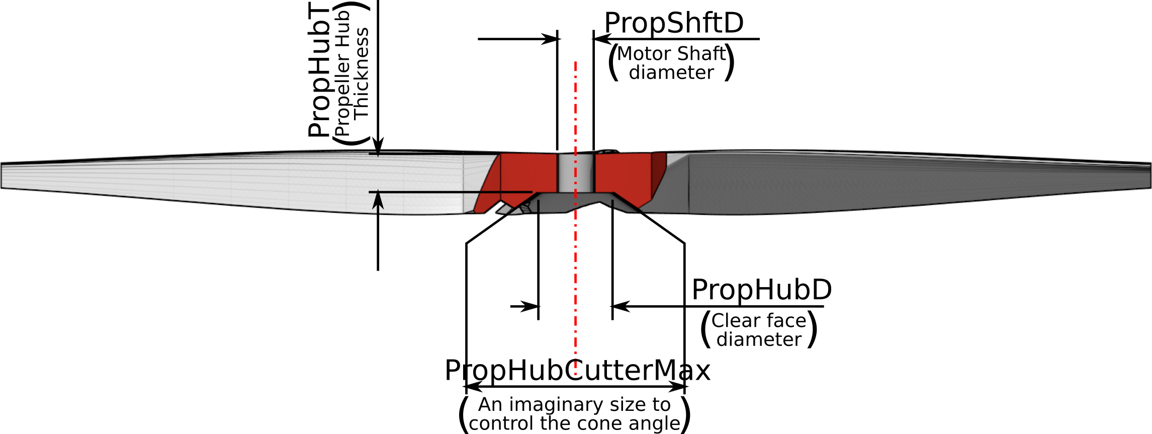
PropShftD: Motor shaft size.
PropHubD: It is not really the hub diameter as such but more an expression of the clear area around the motor shaft.
PropHubDCutterMax: This is a bit of a dumb number. It refers to the imaginary outer diameter of a cylinder used to cut the back of the hub into a slope which will match your motor.
PropHubT: propeller hub thickness.
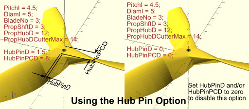
To cater for pinned hubs that appear to be used in small multirotors, the following parameters have been introduced to give an option for pinned hubs. If either or both of these parameters are set to zero the option is disabled. Refer to the diagram below for a demonstration of these parameters in action.
HubPinD: The diameter of pins.
HubPinPCD: The pitch circle diameter of the pins.
There are a number of other parameters but they are variables for use in the code. You are welcome to put numbers in them, but they will be overwritten anyway and have no effect. They are: Poz1, Poz2, StrtAngi, EndAngi, StepLi, StrtWi, and EndWi.
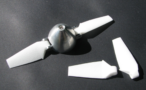
Parametric Folding Propeller Model
Because the folding propellor model was derived from the Multi-blade model decribed above, most of it works the same. This is for the blade only. If you are brave you could try a 3D printed spinner too. I notice there are several on Thingiverse.
You can find the folding prop model on this website here: FoldingPropv2.scad
or Thingiverse here: www.Thingiverse.com - Thing:3506762
As with the Multi-Bladed propeller the airfoil can be changed by substituting a new airfoil coordinate set into the variable called Airfoil_points. The Python script introduced earlier can be used to quickly convert an airfoil .dat file into an OpenSCAD file containing a compatible Airfoil_points variable.
Here is a run down of the parameters used in the Folding prop model.
The fundamentals
Pitch: Use PitchI for Imperial measurement, or PitchM for metric values.
Diameter: Use DiamI for Imperial measurement, or DiamM for metric values.
Blade Maximum Width (mm): MaxChdW
Calculation Factors
Statns: This is the number of stations along the blade where the size and twist is calculated. A higher number will improve the smoothness of the shape but add to the calculations. You may need to fiddle with this when dealing with larger diameter blades to counter the appearance of a gap of pointy bit around the hinge area that sometimes happens. This is demonstrated in the illustration below.
SectRes: The number of intermediate steps between stations. The higher the number the smoother the shape is but it adds significantly to the calculation time.
Pitch Adjustment
The pitch adjustment was originally introduced to de-rate the pitch angle so that my calculated pitch angles would match what I was measuring from a commercial propeller. As it turns out I must have been measuring the commercial propeller pitch poorly and I should have just run with my unadjusted pitch angles. So, leave these both set to 1.0. It is left here because it may be useful for adding washout to the propeller.
PitchAdjHub: Pitch adjustment factor at the hub end.
PitchAdjTip: Pitch adjustment factor at the hub end.
More Blade and Hub Parameters
BldCtr: This is the position of blade centreline about which the blade is scaled and twisted. It is expressed as a % of the distance along the blade chord measured from the leading edge.
SpinHPinRad: This is distance from the shaft centerline to the centreline of the propeller hinge pin.
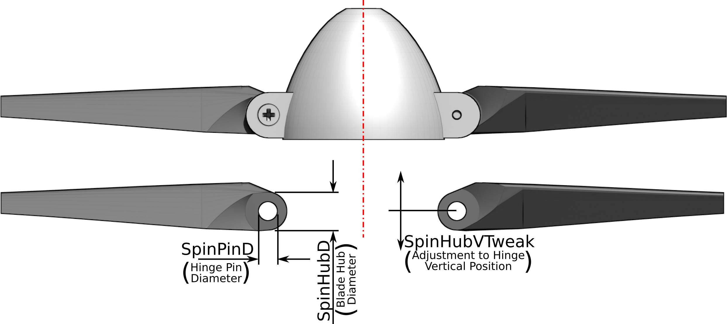
SpinPinD: Hinge pin diameter.
SpinHubD: This is difficult to describe but is the diameter of the bit of the blade base around the pin. See the diagrams for a clear guide.
SpinHL: This is the width of the hinge section.
SpinHubVTweak: this factor will allow you to move the hinge pivot forward or backward on the blade to suit your needs. This may have advantages when making pusher type folding props.
There are a number of other parameters but they are variables for use in the code. You are welcome to put numbers in them, but they will be overwritten anyway and have no effect. They are: Poz1, Poz2, StrtAngi, EndAngi, StepLi, StrtWi, and EndWi.
Other Stuff
The Overall Shape Function
In both models the overall shape of the blade is controlled by a polynomial expression which looks like this.
function BldChrdLen(x) = 1.392*pow(x,4) -1.570*pow(x,3)-2.46*pow(x,2)+3.012*x+0.215;
or

x is the ratio of the position along the blade and the blade length. So the blade tip is x=1.0 and the hub is x=0.
The output is a multiplier that can be used on the maximum blade width to give the width (actually scale) of the blade at any point.
For the shape included with these scripts, the profile was measured off an existing commercial blade.
If you are wanting to design your own shape then the method I used to turn the measured profile into the expression used was quite simple.
- First enter a series of coordinates into your favourite spreadsheeter. Where the X coordinates run from 0 to 1, and the Y coordinates run from 0 to 1. (Alternatively you could use your actual measurements and ratio them later).
- Create an XY scatter plot of your coordinates.
- Adjust your coordinates until you have the shape that pleases you.
- Use the Trendline tool set to calculate a polynomial of whatever order suits your shape.
- The polynomial created can then be transferred to the script.
For instance, here is a completely made up weird profile. The trendline has not matched it too well but given how extreme the plot is that’s to be expected.
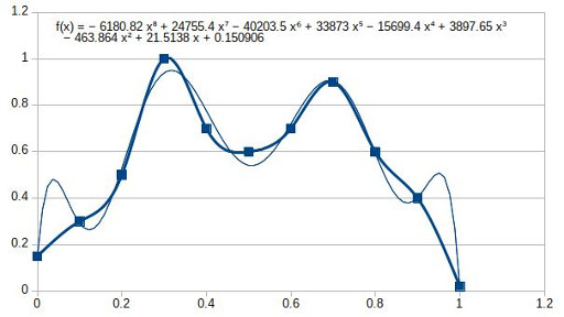
Translating this into our OpenSCAD function gives us;
function BldChrdLen(x) = -6180.82*pow(x,8)+24755.4*pow(x,7)-40203.5*pow(x,6)+33873*pow(x,5)-15699.4*pow(x,4)+3897.65*pow(x,3)-463.864*pow(x,2)+21.5138*x+0.150906;
and here is the result;
What spectacular properties might such a blade have? Probably none.
What’s With the PitchAngAdj(x) Function?
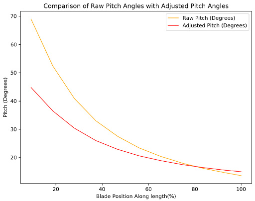
This function was created to try to match some pitch measurements I made off a commercial propeller. The function produces a scale factor to multiply the theoretical pitch by to flatten it or increase it along the length of the blade. The function is just a linear relationship.
function PitchAngAdj(x) = 2*(PitchAdjTip-PitchAdjHub)/Diam*x+PitchAdjHub;
Where PitchAdjTip is the pitch adjustment factor at the tip and PitchAdjHub is the pitch adjustment factor at the hub. As it happens whatever measurements I took of the pitch along the length were not all that accurate, and the theoretical pitch I had initially calculated was fine. So, leaving PitchAdjTip and PitchAdjHub set to 1 will yield a blade with the right pitch.
However, should you wish to experiment with washout at the blade tips, then this function is the place to fiddle around with it.
To illustrate the function in action here is the theoretical pitch versus the adjusted pitch where;
PitchAdjTip = 1.1.
and PitchAdjHub = 0.65.
These Propellers in Actual Use
At this stage I have tested a fixed blade on my FPV Shadow and found that it works well and feels exactly the same as the commercial propeller. Here are some observations;
- The thrust felt the same as the original propeller.
- Noise may have been very slightly down but a small reduction in sound power would probably be barely detectable (especially to my damaged hearing).
- Motor and ESC were all cool when I landed it, so no excessive load on them.
- It appeared the prop windmilled more easily than the commercial one when gliding in with no throttle. To me this suggests slightly better airflow around the prop. I might just be imagining that though.
- Because the prop was windmilling more on final glide in to land, there was some tip strike on landing but no damage to prop or motor mount. The greater flexibility of the 3D printed nylon propeller compared to the commercial propeller was a bonus.
- Because of the greater flexibility of the nylon propellers I was worried that there might be a loss of power due to the blades twisting and feathering. This didn’t appear to happen.
I will be carrying out some slightly more objective tests once I have finish building my test rig. I’d like to try other airfoils, and play with blade numbers and blade shapes too. I’ll put these results up here as I do the experiments.

Note:
This article and associated coding by Hamish Trolove are licensed under a Creative Commons Attribution-ShareAlike 4.0 International License.