Airfoil to OpenSCAD Converter

A short time ago I designed a parametric model for generating 3D printed propellers.
Also on Thingiverse;
Both used the NACA4412 airfoil which I understand to be commonly used for props. This makes a thin blade which is fairly flexible. This may not be a good thing and so thicker airfoils may be desirable to stiffen the blades. To test different airfoils I will need a number of different profiles in an OpenSCAD format.
You can find many different airfoil profiles on the UIUC Airfoil Coordinates Database website. These are available for download as .dat files. The .dat files are just text files with lists of coordinates. With a bit of work these can be converted to a format that OpenSCAD can accept, but this would be extremely boring to do by hand. This seemed like a good target for a python tool which would load the .dat file and spit out an OpenSCAD file containing the airfoil profile.
There is some variation between the ways the .dat files have been structured, but hopefully I have managed to cater for them all.
The converter tool was written in Python3 and does not require any additional libraries other than tkinter which ships as standard with most Python installations.
You can download the Airfoil to OpenSCAD Converter Tool from here: Airfoil-Scad_Converterv3.py
Using the Tool
Get Your Airfoil .dat
First go to the UIUC Airfoil Coordinates Database website and select an airfoil. Download the .dat file.
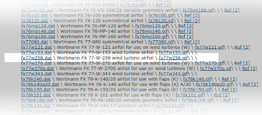
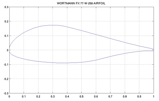
In this case I have randomly selected a Wortmann FX 77-W-258 airfoil which is used on wind turbines. The profile has this shape:
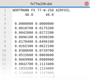
and the format of the .dat file looks like this:
Run the Python Script
Assuming you have Python3 installed, open a command prompt where-ever you have downloaded the Airfoil-Scad_Converterv3.py script and run it with;
python3 Airfoil-Scad_Converterv3.py
This will open a simple tkinter interface:
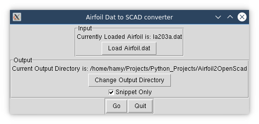
The Interface
- Load Airfoil.dat button opens a file browser dialogue where you can navigate to and select your dowloaded .dat file.
- Change Output Directory button opens a directory browser dialogue where you can select the directory where you’d like the processed .scad file written to. The default is the same directory where the script is.
- Snippet Only tick box allows the user to select between a simple .scad file or a standalone .scad file.
- The simple .scad file option only contains a variable called
Airfoil_pointswhich holds the airfoil point coordinates. This is the default. - The standalone option can be run as an OpenSCAD file to produce an extruded shape from the
Airfoil_pointsvariable. - The “Go” button runs the conversion process to read the .dat file, process it into a .scad file, and write the output. The output .scad file has the same name as the input .dat filename. A message window will pop up telling you the filename and directory where you can find the processed file.
Note: This script is designed on the “Smart User rather than Smart Software” philosophy to keep it simple. If the user tries to load something other than an airfoil .dat file it will report errors to the terminal but won’t crash.
Work with the Output .scad File
Once you have your processed .scad file you can do whatever you like with it.
If you chose the simple default output, you will have something like this.
// Blade airfoil profile.  Replace this as needed.
Airfoil_points = [[0.0, 0.0], [1.1, 17.5], [4.3, 27.2], [9.6, 39.0], [17.0, 49.6], [26.5, 62.2], [38.1, 74.0], [51.6, 87.0], [67.0, 98.9], [84.3, 111.3], [103.3, 122.5], [124.1, 133.7], [146.4, 143.3], [170.3, 152.4], [195.6, 159.8], [222.2, 166.2], [250.0, 170.4], [278.9, 173.2], [308.7, 173.4], [339.3, 171.8], [370.6, 167.3], [402.4, 160.7], [434.7, 152.6], [467.3, 144.3], [500.0, 135.3],

                                  ............

-87.8], [278.9, -86.4], [250.0, -84.0], [222.2, -81.6], [195.6, -78.3], [170.3, -75.2], [146.4, -71.0], [124.1, -67.2], [103.3, -62.4], [84.3, -58.0], [67.0, -52.6], [51.6, -47.9], [38.1, -41.9], [26.5, -37.0], [17.0, -30.7], [9.6, -25.2], [4.3, -17.6], [1.1, -12.7], [0.0, 0.0]];   //fx77w258.dat
This needs to be built into another .scad script to create geometry. The primary purpose for this script was to produce airfoil profiles that could be substituted into the Parametric Propeller Generators shown at the top of the article.
If you chose the standalone option then the output will look something like this;
//fx77w258.scad
// Blade airfoil profile. Replace this as needed.
Airfoil_points = [[0.0, 0.0], [1.1, 17.5], [4.3, 27.2], [9.6, 39.0], [17.0, 49.6], [26.5, 62.2], [38.1, 74.0], [51.6, 87.0], [67.0, 98.9], [84.3, 111.3], [103.3, 122.5], [124.1, 133.7], [146.4, 143.3], [170.3, 152.4], [195.6, 159.8], [222.2, 166.2], [250.0, 170.4], [278.9, 173.2], [308.7, 173.4], [339.3, 171.8],
...........
-62.7], [597.6, -70.7], [565.3, -76.6], [532.7, -81.5], [500.0, -84.7], [467.3, -87.3], [434.7, -88.7], [402.4, -89.7], [370.6, -89.6], [339.3, -89.2], [308.7, -87.8], [278.9, -86.4], [250.0, -84.0], [222.2, -81.6], [195.6, -78.3], [170.3, -75.2], [146.4, -71.0], [124.1, -67.2], [103.3, -62.4], [84.3, -58.0], [67.0, -52.6], [51.6, -47.9], [38.1, -41.9], [26.5, -37.0], [17.0, -30.7], [9.6, -25.2], [4.3, -17.6], [1.1, -12.7], [0.0, 0.0]]; //fx77w258.dat
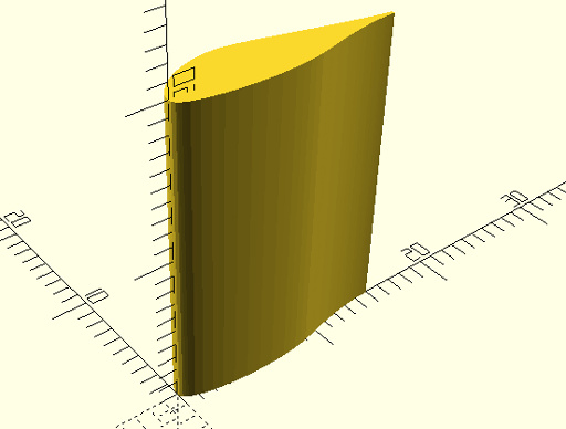
linear_extrude(height=20, twist = 0, slices = 10)scale([15, 15])translate([0,0])scale (0.001)polygon(points=Airfoil_points);
The only difference is that this will render a solid form in OpenSCAD like so …

Note:
This article and associated coding by Hamish Trolove are licensed under a Creative Commons Attribution-ShareAlike 4.0 International License.