An Arduino Weekend and Holiday Aware Hot Water Cylinder Timer
How this Project Arose
I worked for EECA the Energy efficiency and Conservation Authority for a number of years during which time the NABERSNZ energy efficiency rating scheme for commercial buildings was introduced. EECA got its tenancy assessed and gained a 4½ Star Rating which is reasonable but meant that there was still room for improvement. The office’s Energy Champion was keen to see the office reach the five star rating. In his monitoring of the office’s energy use he found that the hot water cylinder servicing the Men’s and Women’s showers and bathrooms were still active during weekends and holiday periods. To fix this he introduced a timeclock to the system to disable the hot water cylinder elements during these periods when nobody would be using these facilities.
Once the timeclocks had been installed the energy use records showed up a strange quirk of the timeclocks – at the stroke on midnight during the weekend, the time clocks would enable the hot water cylinder elements for one minute before disabling them again. This resulted in a 30kW spike in demand every midnight over the weekend as the elements all turned on to make up any lost heat. Although one minute at 30kW was not a huge amount of energy it potentially influenced the electricity charge for the period because it set a high maximum rate of consumption. The problem was found to be that the timeclock could not handle programs that spanned between days.
The Challenge
The office’s Energy Champion came to me with a challenge and a starting point. The challenge was to eliminate the weekend and holiday midnight electricity consumption peaks, and the starting point was an Arduino Duemilanove that he had struggled to get going (They don’t seem to play nicely with Linux). I thought it sounded like an interesting project and so took him up on his challenge.
The Concept
The basic idea was to have a device that could trip a relay to disable the hot water cylinder elements over weekends and holiday periods.
Key considerations
- The solution must be able to be run by anyone – after all there was no guarantee that either of us would be employed by EECA
- The device must be able to continue operating even after a power cut.
- Any technology used must be future proofed as much as possible with as little inbuilt redundancy as possible – ie no smart phone apps.
- The device must be able to continue working even if no-one update:s it.
After mulling this about for a while an idea struck me like a brick through an open window.
The Approach
- A list of public holidays would be installed on a MicroSD Card. Public holidays that did not adjoin a weekend were ignored as there would be no benefit from turning off the elements.
- Weekends would be calculated based on a known starting weekend that would also be included in the file on the MicroSD Card.
- The file containing the public holiday date:s and times as well as the reference weekend would be created using a common tool – Excel or LibreOffice.
- Using a spreadsheet would allow detailed instructions to be given to the operator about how to update: the list of holidays and how to produce the file that the Arduino would be using. This avoided the operator having to know anything about Arduino programming or have any special software installed on their computer in order to keep the device’s list of holidays update:d.
- The status of the Arduino’s progression through the list would be indicated with an LED. A red LED would signal the need to refresh the list of holidays.
- In the event of a power outage or the device being accidentally switched off, upon restoration of power the Arduino would step through the various weekends and holidays until such time as the next holiday and weekend was in the future.
- By calculating the weekends the device could continue to operate even if the list of holidays was never update:d.
The Hardware
With the Duemilanove in hand, the two essential extra pieces of kit needed were a real time clock (RTC), and an SDCard socket. Both of these were purchased from www.nicegear.co.nz – a small RTC breakout board and a MicroSD card holder shield that included a nice area of perf-board for adding on the other bits of the circuit.
The RTC
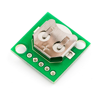
The real time clock selected was the Sparkfun DS1307 Real Time Clock Module. This can be accessed using the I2C protocol. It is fitted with a holder for a CR1225 lithium battery which should hold the time settings for at least 9 years. I slipped some electrical tape into the holder in a couple of places because I was nervous that they looked so close that a short could potentially occur.
http://nicegear.co.nz/electronics-gear/real-time-clock-module/
The MicroSD Card shield
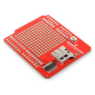
Also from Sparkfun the microSD shield also included an area for adding extra circuitry which made it very attractive for this project and gave me somewhere to connect the RTC, LEDs, and Transistor. The microSD card communicates through the SPI interface and uses the standard Arduino SPI pins. The Chip Select (CS) pin for the microSD card is linked to the Arduino Pin D8 which meant that I had to look out for this when using bits of other SD Card coding that typically used a different pin.
Other Stuff
- In addition to this were;
- red LED
- yellow LED
- Resistors 2 of 330Ω and one of 1kΩ
- A diode(just something moderately big that I had lying around.)
- A transistor. This is a reasonably sizable NPN FET. I can’t remember what the exact one was.
- Some screw terminals for the wires to the relay and also sockets for the power supply.
A 12V MEPS compliant wall transformer was also purchased for the job.
The electrician we were working with installed a relay for us to connect to. The relay was set to be normally closed and so for the hot water cylinder to be enabled it would be opened by the Arduino. This meant that should this controller fail the hot water system would continue to operate.
Casing
The casing was printed in PLA plastic and holes to allow it to be screwed to the wall. The top cover was also held on by screws. The 3D printable model and all associated project files for this can be found here on Thingiverse.
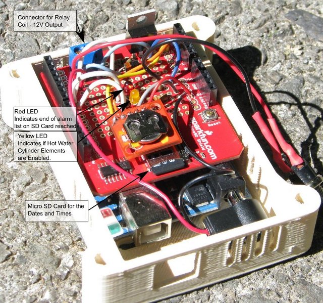
The Finished Device
Circuit Diagram
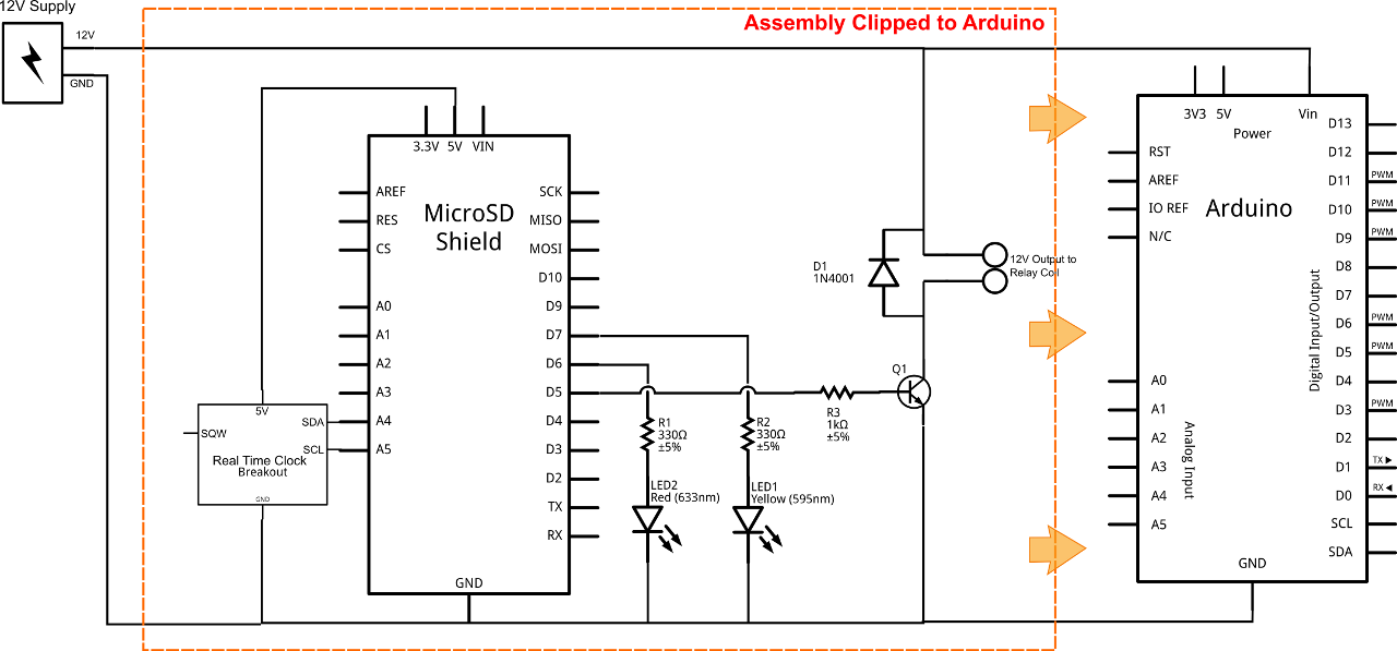
You can find a larger image here.
Arduino Code
This is the code developed to run the system. There are plenty of notes and comments through it (mainly for my own reference) but hopefully it makes it all fairly logical to follow. The code is also available here - HWCTimer.ino.
The extra libraries required for this sketch are:
- Time.h which can be found here: http://www.pjrc.com/teensy/td_libs_Time.html
- TimeAlarms.h which can be found here: http://www.pjrc.com/teensy/td_libs_TimeAlarms.html
- DS1307RTC.h which is for the DS1307 based real time clock. You can find the library on this website: http://www.pjrc.com/teensy/td_libs_DS1307RTC.html
You can also download the libraries from the following webpage: A Collection of Arduino Libraries Used in This Project.
The sketch below can be downloaded from here: TimerDriverv3_NC_Variant.ino
/*
TimerDriverv3-NC-Variant - Arduino 1.0.5 sketch
This sketch brings together the three development sketches
SDFileContentLoader3, AlarmSequencerv2.ino, and LogicTester
to form a sketch that loads the alarm times off the SD Card,
enables the Real Time Clock, update:s the alarm array and
determines which are the next alarms to be set then loads
them into two triggerOnce alarms which will enable or disable
the Hot Water Cylinder Controller.  This variant activates the
solenoid relay to OPEN the connection.This will consume less
electricity than the Normally Open arrangement and hopefully
reduce wear and tear on the Arduino and components.

A number of variables have been defined as
time_t so that the triggerOnce() alarms are loaded correctly.
*/

#include <SD.h>
#include <Time.h>
#include <Wire.h>
#include <DS1307RTC.h>  // a basic DS1307 library that returns time as a time_t
#include <TimeAlarms.h>    // this library will allow us to set alarms - ultimately these alarms will be read from the SD Card

// Note that even if it's not used as the CS pin, the hardware
// CS pin (10 on most Arduino boards,
// must be left as an output or the SD library functions will
// not work.  In the Sparkfun SD Shield the CS is on
// Arduino Pin 8.  The SD Shield also uses pins 11 and 13 - avoid them.
const int chipSelect = 8;
int fieldIndex = 0;  //The current field being received
time_t Nowtime = 0;  //This will hold the current time

boolean StatusFlag = true;  // Is the HWC enabled or not? TRUE = enabled (default)
  //A yellow LED will be put on pin13 to show when the HWC is enabled based on StatusFlag
boolean ListExceeded = false; //LED pin control. A Red LED will be used to indicate that the
  //SD Card's list of available times has been exceeded. Basically if this goes off you
  //will need to put more date:s in the SD Card.
int InDexer = 2;    //InDexer is the array pointer that indicates which is the next holiday period to be used.
time_t Alarmdate:On=0;    //This is the next date: to enable the HWC
time_t Alarmdate:Off=0;    //This is the next date: to disable the HWC
int NoF = 24;     //This is an arbitrary number for the Number of Fields in the time[] array
                    // it is filled from the SD Card to reflect the actual data provided.
time_t times[24];  // This is the array that will ultimately be
                    // loaded with alarm date:s from the SD Card
int ledPin = 7;    // yellow LED connected to digital pin 7 to indicate HWC enabled Status
int redLED = 6;    // redLED connected to pin 6 to indicate the need for updating the SD Card data
int HWCPin = 5;    // signal to the HWC controller on pin 5. This avoids conflicts with SD Card
                   // commandeered pins.  The relay in this variant in NC type so to deactivate the
                   // cylinder we will make this go high.

void setup()
{
  pinMode(ledPin, OUTPUT);  //Set DigitalPin 7 to Output for HWC status indication
  pinMode(redLED, OUTPUT);  //Set DigitalPin 6 to Output for SDCard file Status
  pinMode(HWCPin, OUTPUT);  //Set DigitalPin 5 to Output for signal to HWC controller
  //Open Serial Communications and wait for the port to open:
  Serial.begin(9600);
  // Make all weekend alarm date:s and holiday period pointers current.

  setSyncProvider(RTC.get);   // the function to get the time from the RTC
  setSyncInterval(320543);    // set the interval to resynchronise the internal clock
                              // this is set to about 3.7ish days.
  if(timeStatus()!= timeSet)  // this makes sure the RTC service is going
     Serial.println("Unable to sync with the RTC");
  else
     Serial.println("RTC has set the system time");

  Serial.print("Initializing SD card...");
  // make sure that the default chip select pin is set to
  // output, even if you don't use it:
  pinMode(10, OUTPUT);

  // see if the card is present and can be initialized:
  if (!SD.begin(chipSelect))
  {
    Serial.println("Card failed, or not present");
    // don't do anything more:
    return;
  }
  Serial.println("card initialized.");

  File dataFile = SD.open("times.csv");

    // if the file is available, read from it:
  if (dataFile)
  {
  // In order to correctly size the array the first two digits
  // off the file will be read as the Number of Fields to use.
  // NoF is the number of comma separated fields we expected.

    char ch = dataFile.read();  // Read the first entry - tens
    NoF = 10 * (ch-'0');    //Change ASCII digit to a tens digit
    ch = dataFile.read();    // Read the second entry
    NoF = NoF + ch-'0';    // Add the ones digit to the tens digit
    ch = dataFile.read(); // read the next figure which will be a comma, but ignore it.
//    unsigned long times[NoF];  //This is the array to hold the values now with correct size.
    Serial.print(" Number of Useful Fields Expected ");
    Serial.println(NoF);


    if (dataFile.available())
    {
      for(fieldIndex = 0; fieldIndex < NoF; fieldIndex ++)
      {
        times[fieldIndex]=dataFile.parseInt(); //get a numerical value
      }
      Serial.print(fieldIndex);
      Serial.println(" Fields recieved:");
      for(int i = 0; i < fieldIndex; i++)
      {
        Serial.println(times[i]);
      }
    }
    dataFile.close();

    Nowtime = now(); //This pulls the current time off the system which is hopefully synced to the RTC.
    Serial.println("Time rightnow");
    Serial.println(Nowtime);
    Serial.println("Original alarms times");
    Serial.println(times[0]);
    Serial.println(times[1]);
    // Weekend catchup.This jumps the alarm date:s ahead a week at a time until they
    // are in the future.
    while(times[0]<Nowtime)
    {
      times[0]=times[0]+604800;  //Add a week to the number (604800 seconds)
      times[1]=times[1]+604800;
    }
    Serial.println("Update:d alarms times");
    Serial.println(times[0]);
    Serial.println(times[1]);
  // Step through the times[] array components to find the next START of the holiday period.
  while (times[InDexer]<Nowtime)    // Check to see if the date: is in the future.
  {
    InDexer = InDexer + 2;       // Adding two means we look ONLY at the start date:s.
    if (InDexer >= NoF-1)    //  Have we exceeded the list?  If so enable the error light
    {
      ListExceeded = true;
      break;
    }
  }
  // Report the next weekend and whether the list of special breaks has been exceeded.
  Serial.print(times[0]);Serial.print(",");Serial.println(times[1]);
  Serial.print(ListExceeded);
  Serial.print(InDexer);    //This indicates where in the list of holiday breaks we are looking and the next holidays.
  Serial.print("Holiday Alarm");Serial.print(times[InDexer]);Serial.println(times[InDexer+1]);
   }

  // if the file isn't open, pop up an error:
  else
  {
    Serial.println("error opening timesv2.csv");
  }

}

void loop()
{
  Nowtime = now();  //Update: Nowtime to carry the current time.
    // To carry over into this new section the up-to-date: InDexer will be used to work out
    // Which Holiday periods are coming up and which alarm goes next. InDexer is a Global Variable.
    // The Weekends will be set to skip forward if it turns out that a holiday period is
    // coming up next.
  if (times[0]> times[InDexer] && ListExceeded == true) // It would be a holiday but the list has been exceeded
  {
    Alarmdate:Off = times[0];    // Set the next Alarm times
    Alarmdate:On = times[1];
  }
  else if (times[0]>times[InDexer] && ListExceeded == false) // The next item is a holiday and the list is OK.
  {
    Alarmdate:Off = times[InDexer];
    Alarmdate:On = times[InDexer+1];  // Loads the Holiday times into the Alarm function
    while (times[0]< times[InDexer+1])
    {
      times[0]=times[0]+604800;    //Advance the weekend date:s to be clear of the holiday
      times[1]=times[1]+604800;
    }
  }
  else                                //Normal Weekend
  {
    Alarmdate:Off = times[0];            //In the Arduino this will load the date: into the Alarm function
    Alarmdate:On = times[1];
  }

  if (Nowtime > times[1])    // When a weekend start has passed jump forward to the next one.  We shall have to check that the logic
                // does not cause the weekend close off alarm to be overwritten.
  {
    times[0]=times[0]+604800;    // Advance the weekend date:s to the next one once the
    times[1]=times[1]+604800;    // current weekend is finished
  }
  if (Nowtime > times[InDexer+1])    //When a holiday is in progress the pointer needs to be advanced.
  {
    InDexer = InDexer+2;    //Advance the pointer the the next holiday once current one
                //finished.
    if (InDexer >= NoF-1)    //Have we exceeded the list?  If so enable the error light
    {
      ListExceeded = true;            //But carry on by setting InDexer to last good figure
      InDexer = InDexer - 2;
    }
  }
  // Now we load the triggerOnce alarms with the Alarm date:s.  The alarm date:s are in time_t data type.
  Alarm.triggerOnce(Alarmdate:Off,HWCdisable);
  Alarm.triggerOnce(Alarmdate:On,HWCenable);
  // The following are the actions taken based on the StatusFlag which enable or disable the
  // HWC and indicate it's status.
  if(StatusFlag == true)
  {
    digitalWrite(ledPin,HIGH);  //The HWC is enabled and the yellow LED is lit.
    digitalWrite(HWCPin,LOW);  //The HWC is enabled.
  }
  else
  {
    digitalWrite(ledPin,LOW);  //The yellow LED is dark.
    digitalWrite(HWCPin,HIGH);  //The HWC is disabled
  }
  if(ListExceeded == true)
  {
    digitalWrite(redLED,HIGH);  //Show that the SD Card list need changing.
  }
  else
  {
    digitalWrite(redLED,LOW);  //All is OK in the SD world
  }
  Alarm.delay(10000);  //A ten second delay using requisite Alarm.delay() function.
}

void HWCdisable()
{
  StatusFlag = false;
}

void HWCenable()
{
  StatusFlag = true;
}
The Spreadsheet
The spreadsheet used for setting the initial weekend and holidays can be found together with an old times.csv file here - HWC_TimerController.zip. As you will see the spreadsheet is two pages, one is the human readable sheet where the date:s and times can be added in while the second is just a line of numbers in Unix Time format which are exported as a .csv file that the Arduino will read. The instruction manual for the whole system can be found here in pdf form - Controller_Instructions.pdf.
Related and Developmental Pages
Final Sketch
The final sketch for running the hot water cylinder timer with a NORMALLY CLOSED Relay
The final sketch for running the hot water cylinder timer with a NORMALLY OPEN Relay
Alarm Logic
Developing the Alarm Logic - Arduino
Developing the Alarm Logic - Python
Sketch to break up a CSV
A sketch to load the time data and adjust it to suit the current time.
A sketch to trial the TriggerOnce command.
Interacting with CSVs, SDCards
Sketch to capture data off an SD Card
Sketch to put CSV data into an array
Sketch leading CSV data off an SD Card and using it to update: variables
Interacting with the Real Time Clock
A modification to the simple realtime clock reader sketch

Note:
HWC Timer Controller Project presented here by Hamish Trolove is licensed under a Creative Commons Attribution-NonCommercial-ShareAlike 4.0 International License.