Solar Charger for LiPO Batteries With Low Voltage Cutoff
There are a number of projects where a solar powered LiPO battery would be useful, but need the additional protection of a low voltage cutoff to avoid killing the battery or worse, starting a fire. This project describes the circuit for solar charging a single cell LiPO battery which is powering a piece of kit but preventing it from discharging below 3.7V. 3.7V is the recommended lowest voltage for a single cell LiPO under no load.
In this case, the battery is a 1000mAh single cell LiPO to power a weather station outdoor unit. The battery was recovered from a disposable Vape thing that some git had kindly biffed out the window onto our tinder dry berm as they drove past our place. Nice of them! Until I’d opened the thing I’d not realised they had LiPO batteries in them and certainly not one with such a large capacity. So, one raspberry flavoured LiPO battery recovered for a much more useful application.
Components
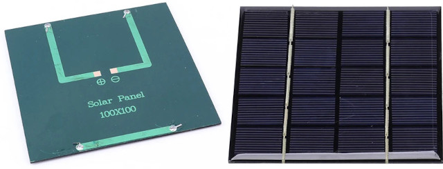
Solar Panel: 3W 5V Polycrystalline Solar Cell
The ones available from one of the Aliexpress suppliers are 100x100mm and have nice easy to solder pads on the back for adding whatever wire arrangement you want.
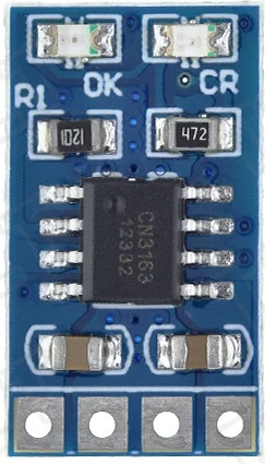
Charge Controller: TZT MPPT Solar LiPO Battery Charge Controller 1A 3.7V
The charge controller is a tiny circuit board with a couple of LED charge indicators, and is fairly versatile. If you have higher voltage solar panels, it is recommended to use a DCDC buck converter to bring the input voltage down to 5V.
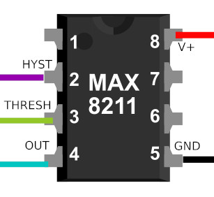
Voltage Monitor: Maxim MAX8211 Microprocessor Voltage Monitor with Programmable Voltage Detection
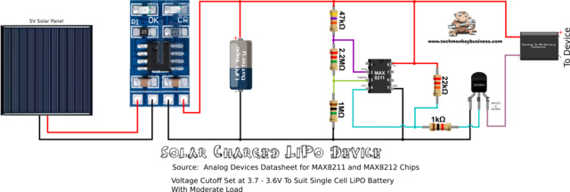
When they say Programmable Voltage Detection they really mean, set up a voltage divider around it to set the target voltage cutoff. The Datasheet has good guidance on calculating the resistors you will need. The resistors used are in the megaohm range and so the losses through the divider are tiny. The voltage monitor is an 8-pin integrated chip. The output (pin 4) from the chip is a simple drain which is open or closed depending on whether the voltage threshold has been reached at pin 3.
Transistor: 2N2222 or 2N3904
This is for shutting off the load. Any moderate NPN Transistor will do the job. Just match it to the load being handled.
Resistors: 47kΩ, 2.2MΩ, 1MΩ, 22kΩ, and 1kΩ
Other stuff:
To make life easier here are some suggested bits and pieces to include.
8 pin IC socket
Some socket headers
Screw terminals
Protoboard
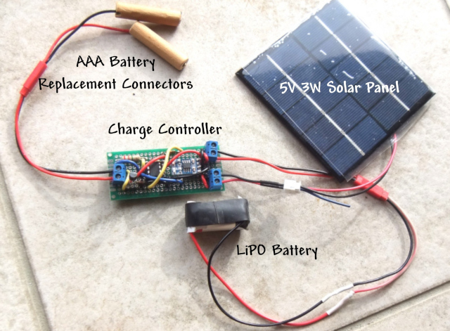
You will also want to make something up to connect into the device you’re powering. In the case of the weather station I need to use a dummy battery pack. This is a set of dowel stubs with screws in the ends to act as the battery terminals which can drop in place of AA batteries.
Circuit Diagram
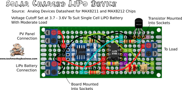
Protoboard Layout
There are a couple of things to note about this layout:
- The MAX8211 integrated circuit is installed in an 8-pin IC socket for stress free soldering.
- The transistor is also seated firmly in set of socket headers. Again this is for stress free soldering.
- Although it is hard to see in this diagram, the charge controller board is also mounted into a set of header sockets. All I needed to do was solder in some pins on the underside of the charge controller board. This makes it super easy to build.
- All connections off the board use screw terminals. This is simply to make it easier to assemble the device when it goes into a case.
Testing
Because so many components were socket mounted or screw connected, this made tracing the connections easy when continuity testing before installing the controller board, MAX8211, and transistor. It also meant I could test the voltage on the voltage divider without the IC being present.
Without the charge controller installed, but with the MAX8211 and transistor installed, I could test the operation of the cutoff by using a variable voltage power supply on the LiPO battery connection terminals and looking at the voltage on the load connection terminals.
Once you have the charge controller installed, and battery connected, the solar panel can be connected. You should see the charge controller LEDs light up. As it charges it will show a red LED and once fully charged, it will light the green LED.
Hopefully this is useful to you in your own project that requires remote low voltage power.


This design by Hamish Trolove is licensed under a Creative Commons Attribution-NonCommercial-ShareAlike 4.0 International License.
