Robotics 1e - More mBot Sensors
To go back to the Overview page click here.
To go to The Next Session - Robotics1f - mBot Sensor lucky-Dip
To download this as a .pdf:

Last time we explored the capabilities of the Ultrasonic Sensor.
This time we’ll try the line following sensor and test its ability to follow some different lines and paths.
Introducing the Line Following Sensor
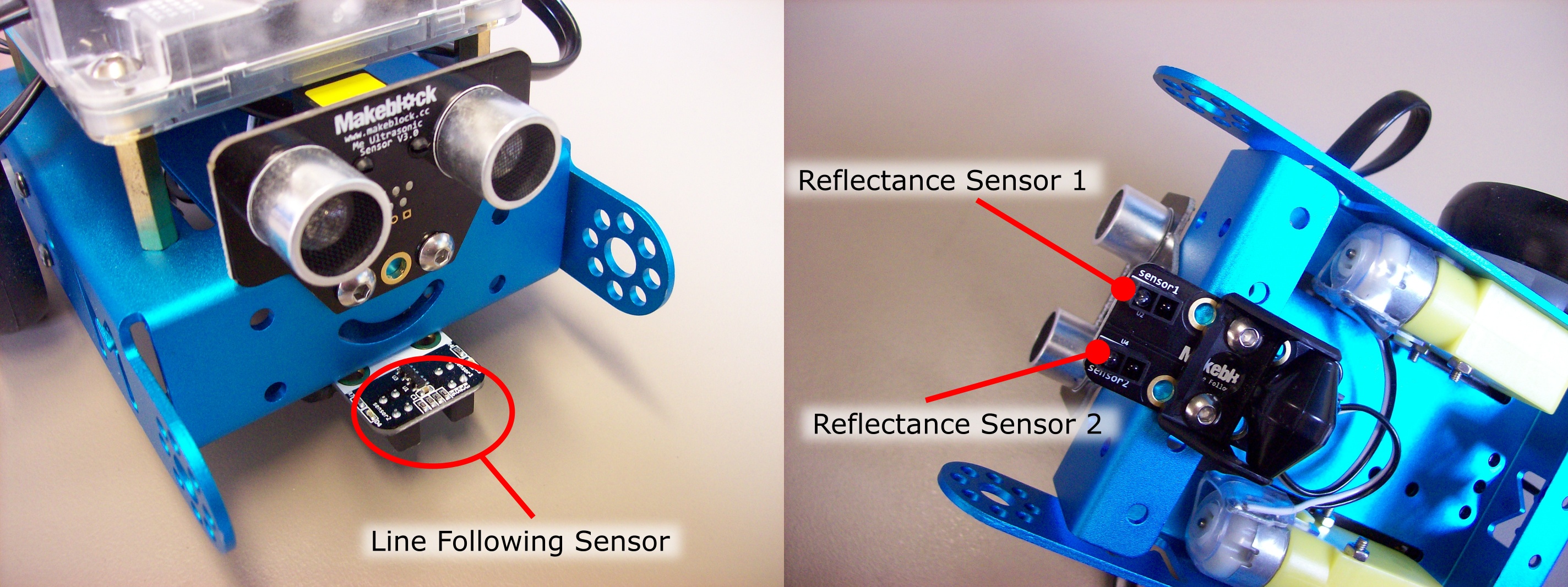
The line following sensor allows the mBot to detect edges and navigate along a thick black line (or a white surface). The sensor is comprised of two Infrared reflectance sensors that detect the reflectance of a surface near them. Each sensor is made up of an infrared transmitter to produce a beam of infrared light, and an infrared light detector mounted beside it to detect that same light if it reflects off a surface.
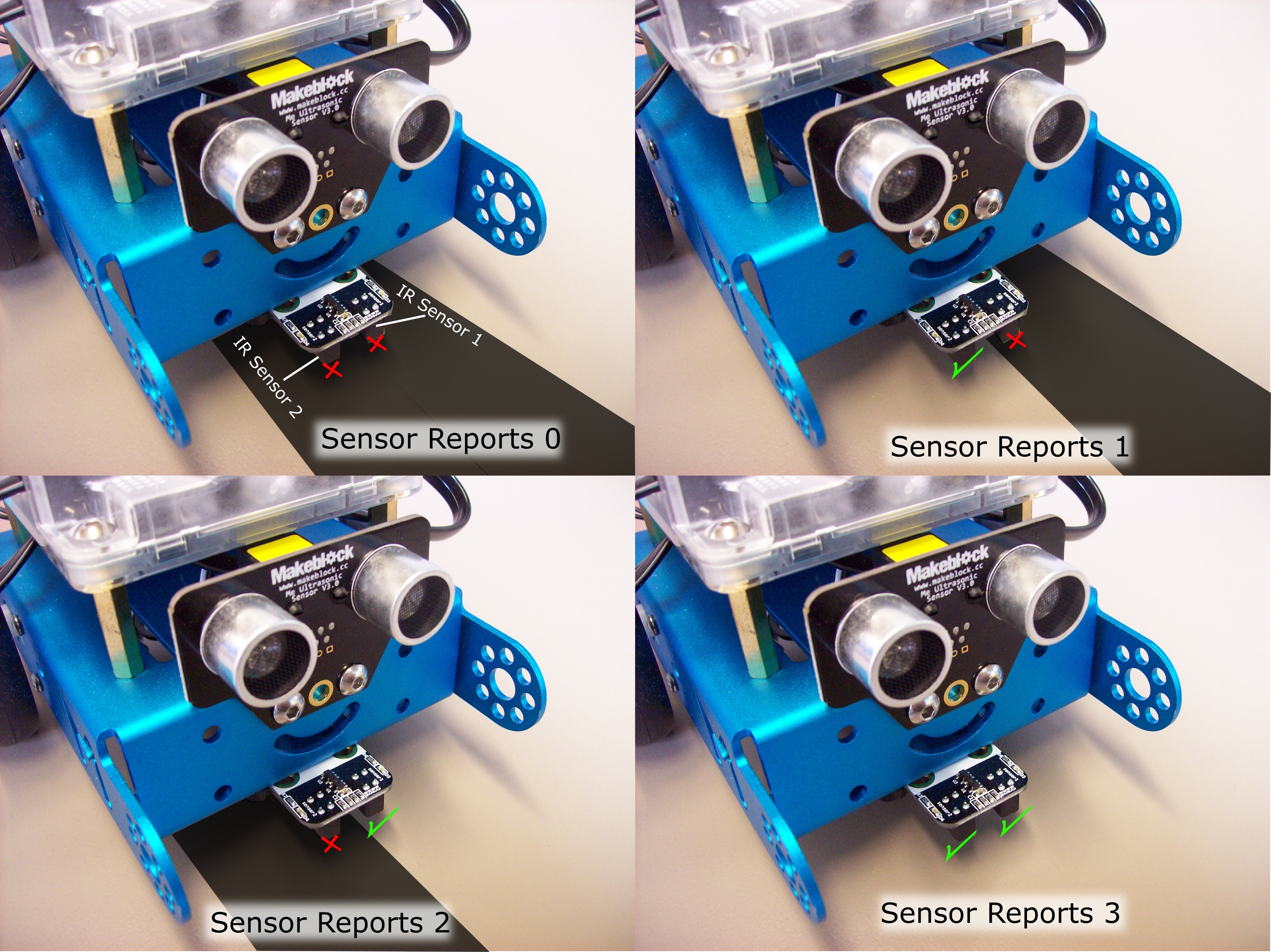
So, if one of the Infrared reflectance sensors is over a black surface there will be very little light bounced back into the infrared light detector which will report a zero value. If the Infrared reflectance sensor is over a white surface there will be a great deal of light bounced back into the infrared light detector which will report a positive number. Having two sets of these infrared reflectance sensors means the line detection sensor can determine;
- when both infrared reflectance sensors are over a black surface (or over an edge),
- when both infrared reflectance sensors are over a white or light coloured surface with some reflectance, and
- when one or other of the infrared reflectance sensors are over a black surface and the other over a light coloured surface – i.e. the edge of a line.
Here is what the line following sensor reports for the different conditions.
To use the line following sensor in our programming we just use this block.

The block is designed to fit into the standard Scratch Operator and Control blocks. The line follower block will output a number from 0 to 3 based on the state of the two sensors as shown above. So we can use this output where a number between 0 and 3 can influence particular events. Here are some examples.
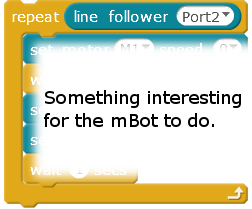
In this case the output from the line following sensor will influence how many times the loop will run.
For instance if the line sensor is fully over a black line it will not do anything within the loop because the output from the sensor is 0.
In the case of the line sensor not being over the line, it will repeat the actions in the loop 3 times.
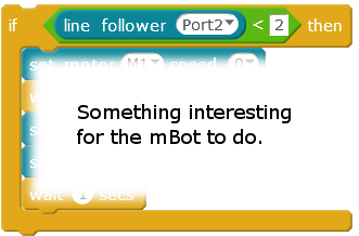
In this case the mBot will do the actions contained with the if block if the line following sensor is over a black line (or dark surface) or where the left side infrared sensor (sensor 1) is over something dark but the right side sensor (sensor2) is over something white(ish).
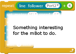
You can use the output from the line follower in mathematical operations.
In this case the output is being added to the number 4 to control the number of times a loop is executed. The loop will run between 4 and 7 times depending on whether the mBot line sensor is over a dark line or not.
Let’s Test the Line Following Sensor
Let’s look at the line following sensor and how we can make use of it. Faced with a new sensor this is the type of approach you would use to work out how to use it.
Once the sensor is connected see what the raw output looks like.
Setting up a test
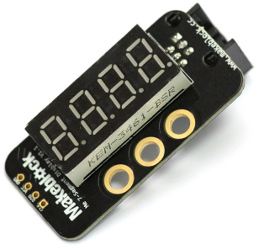
To test the line following sensor’s raw output we will make use of the nifty 4-digit display we used last time. If you don’t have one of these you will need to use the onboard LEDs to give some indication of the data being supplied by the line following sensor.
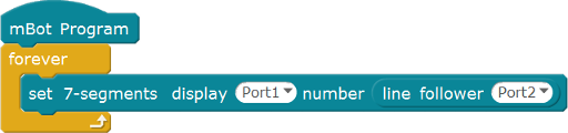
Connect the four digit display to Port 1 on the mBot.
Create a simple program to read the Line Follower and display the output. Upload this to the mBot and see what figures it outputs as you put something black and something pale coloured under the sensor and under one or other of the two Infrared sensors.
Let’s test its sensitivity.
Here are some simple tests to try with this arrangement. The 4-digit display will show the numbers 0,1,2, or 3 depending on which infrared sensor is detecting a light surface.
- Test how far away the surface has to be for the display to read “0000” no matter whether it is a light coloured surface or not. Is this useful?
- How wide does the line have to be for the sensor to detect it reliably.
- How stable is the reading?
- What if the room is bright?
- What if the room is dark?
- How light does the surface need to be for it to tell the difference between it and a dark surface?
- What does it do if faced with a highly reflective surface such as a mirror or polished surface?
Do we know more about the limitations of this sensor?
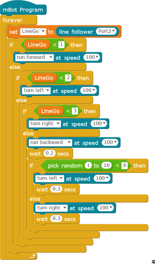
Following a Line
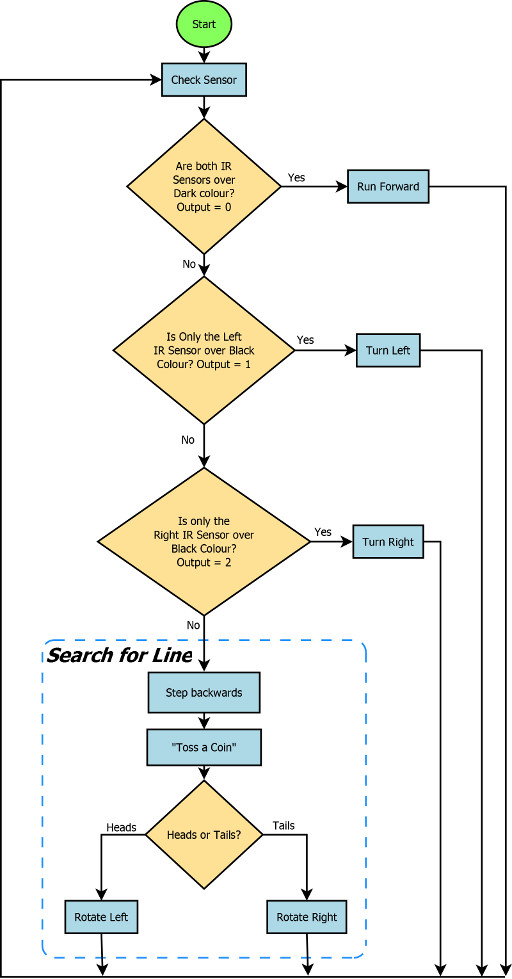
Let’s recreate the line following behaviour of the default program. The program requires the following decisions to be made by the mBot.
- If the sensor has both Infrared Sensors over a dark surface, then it is on track and can run forward.
- If the sensor has only got the left infrared sensor over the line then it will need to turn left to get back onto the line.
- If the sensor has only got the right infrared sensor over the line then it will need to turn right to get back on track.
- If both infrared sensors are over a light coloured surface then it is off the line and will need to search for the line.
Logic for Line Following
Here is the flowchart of the logic being used.
Here is the Scratch program to do this.
You will notice we are using Less-Than operations rather than Equal To operations. While this is not important for this example, it is better practice because it allows for small errors in the sensor output data being compared against. For instance if the line follower sensor were to output a value of “0.999993” or “1.00002” this is not the same as “1” as far as the controller is concerned and so using a block like the following would not trigger the right actions even if that was what we wanted.
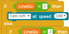
By using Greater-Than and Less-Than conditions makes our robot better able to handle the non-perfectness of the real world. After all Less-Than 2 is a lot bigger target than getting exactly Equal To 1. So the equivalent block that can handle a sensor output value of “0.999993” or “1.00002” would be:
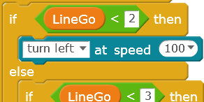
For sensors that output finer resolution numbers we might set the comparison number to “1.3” say rather than “2”, but because our line Following Sensor outputs whole numbers we use the “<2” to pick up an output of “1”.
Your Challenge
OK, now that we have a line following program in place, try out different paths for the mBot and see what is does at junctions. Use bits of black paper to make a course. If you create a curved path, how sharply can it turn before it gets confused?
If your mBot is lost and needs to find the line again create a method to help it search for the line. Try out different methods.
That’s it for This Session
Next time we will look at some of the other components for the mBots and investigate what they can do.


This document “Robotics1e – More mBot Sensors” by Hamish Trolove is provided under a creative commons license - Attribution, Share Alike.