Achieving a Square Map Grid in QGIS

Recently there have been some changes to the regulations governing the use of UAVs and model aircraft in New Zealand. This is a response to the rapid rise of ownership and use of model aircraft of one sort or another, and the irresponsible use of them by certain elements. I was keen to get to grips with GIS software and so a project to producing a printable map showing the airspaces and areas of interest to the members of the local Wellington Model Aeroplane Club seemed like a good exercise.
What I am trying to do is fairly basic but it has been a bit of a steep learning curve to begin to get images from the GIS software I am using. Unfortunately the solution to the problem outlined below is so simple and fundamental that you never see it spelled out for the complete newby like me. So I am writing this to help remind myself how I solved certain fundamental problems I encountered as I start out on this project.
The software I am using is the open source QGIS 2.2 package (formerly know known as QuantumGIS). You can find it here; http://qgis.org.
The topographical maps I am using in this example have come from Koordinates.

So here is the first problem I encountered: My maps are all squashed!!
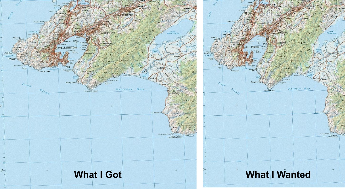
The first problem I encountered when setting out on this exercise was that the map of New Zealand looked somewhat squashed from the shape I was familiar with. We are on a fast moving plate boundary here, but it is not so fast that the shape of the country has changed much since I last looked at a map.
The reason for this flattening is to do with the Coordinate Reference System (CRS) being used and the projection. The flat topographic maps of New Zealand that I am familiar with has squares that are 10 km on a side that look square. These paper based topographic maps use the NZDG 2000 map grid. A project in QGIS can be one of many CRS systems, and so the topographic maps are distorted to fit the CRS system of the project. One of the most common CRS systems is the WGS84. When my topographic map images are fitted to the WGS84 system the marked grids become flattened.
The solution to the problem is to set the Project CRS to match a CRS that will give me the nice square grids that I am familiar with. Because this is a New Zealand dataset, the appropriate CRS is the NZDG 2000 system.
Here are the steps I followed to achieve this and get square grids again.
Finding the initial state.
Firstly, here are the various initial properties of the project and added layers to help set the scene.
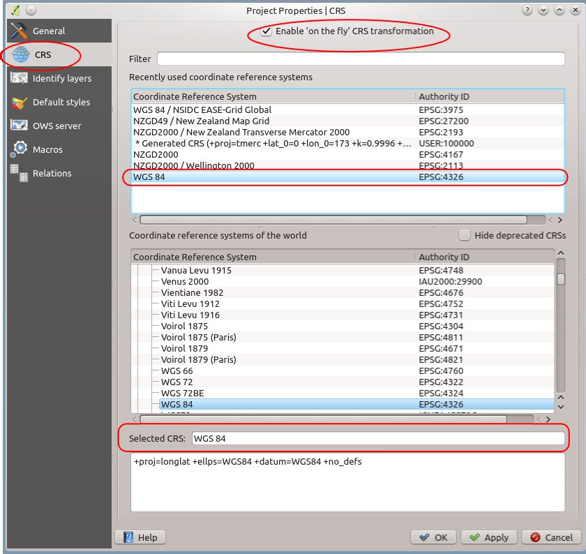
Below is the Project CRS screen. You can get to this through the menu bar by selecting Settings>Project Properties and then going to the CRS screen. As you can see the coordinate reference system is set to the common WGS 84. Also note that the Project settings have the “Enable “on the fly” CRS transformation” option ticked. This means that any new layers added to the project will automatically be adjusted to suit the Project CRS.
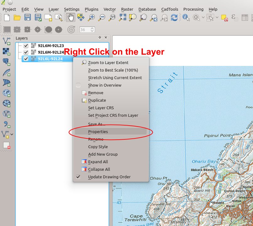
I have added three topographic map raster images to the project. Each image is a separate layer. If I want to find out what the CRS is for the layer, I need to look at its properties. Right click on the layer and select “Properties” from the pop-up menu.
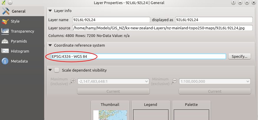
Under the “General” tab, the CRS is listed. In this case it is listed as a WGS84, which is what the project CRS is. It is worth noting that had the topographic raster image been in another CRS, it would have been reported here. Although the project is set to automatically adjust the layers to match the project CRS, the layer still retains its original CRS data. The layer would need to be saved as a new file if it was required to be using a different CRS.
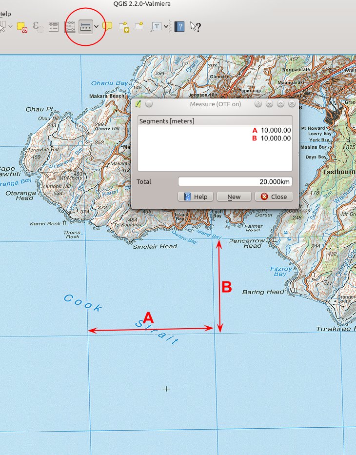
The image below illustrated the problem. The grid which should be a square representing 10km on a side, is quite badly shortened according to the WGS84 system. The measuring tool confirms that it is still 10km on a side. If I wanted to print this image out and give it to someone to use, then the shortened image may cause them problems if they try to scale distances off it, so we need it to be square.
The Solution
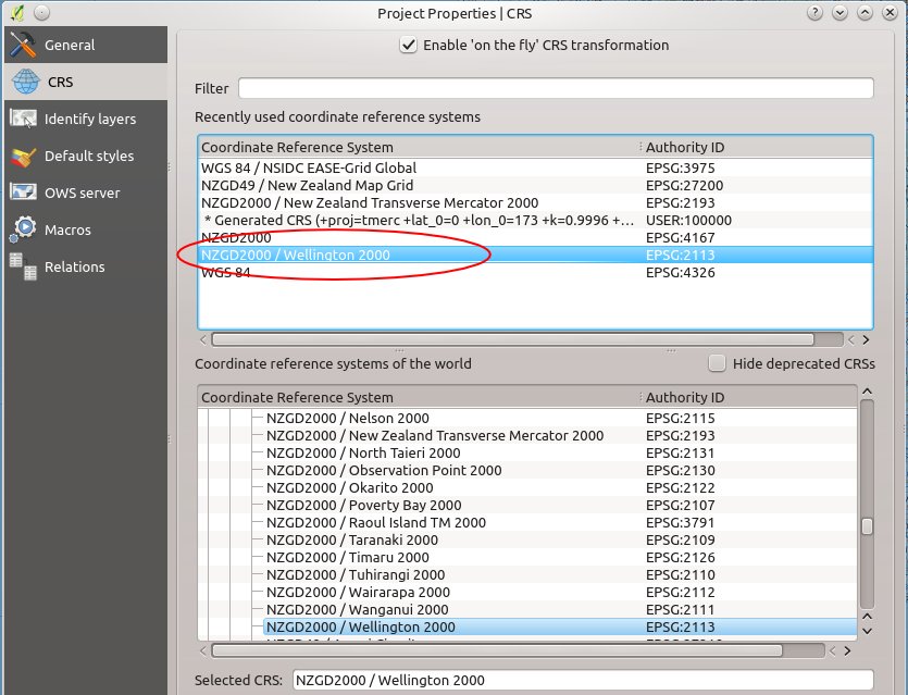
So we go back to the Project CRS, and change it to the NZGD2000 coordinate reference system, and in this case I have chosen one that is focused around Wellington, seeing as these topographical maps are for the Wellington region.
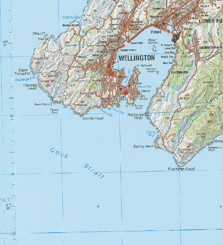
After a bit of churning on my old computer, the image suddenly pops out with a square grid. Yay. Again the measuring tool confirms that the grid is still 10km on a side. Any new layers added to the project will automatically be adjusted to the NZDG2000 / Wellington 2000 CRS and will line up exactly with the features on this map.
For any other location in the world it is a matter of finding out what the local CRS is. QGIS has a large list of them so there will be something appropriate available.