MCP121 Based Solar Engine BEAMbot

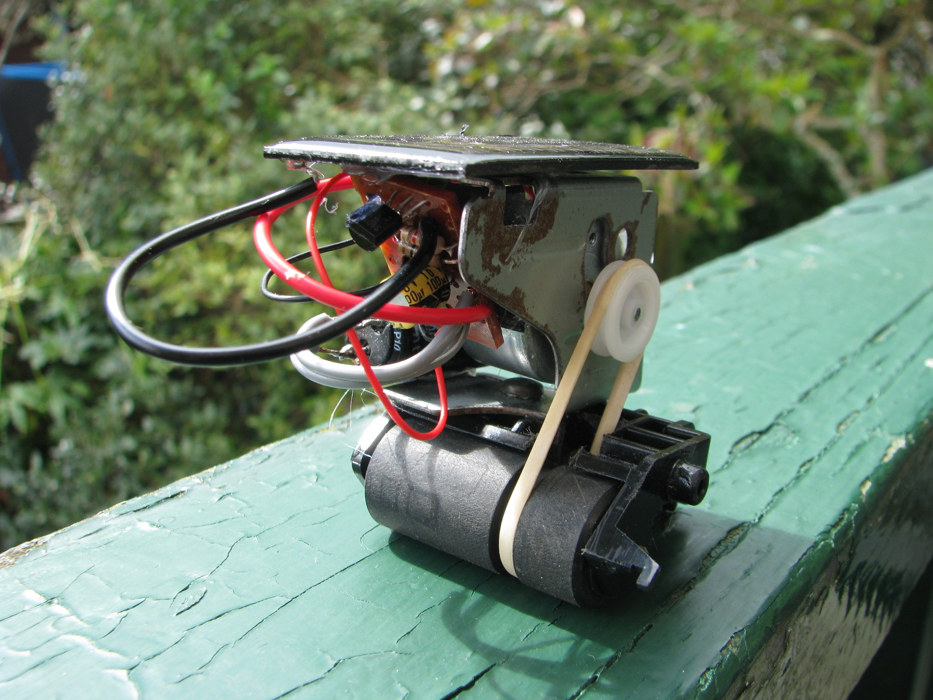
One of my first introductions to the wonders of electronics (true electronics, not what they taught me in school) was David Hrynkiw and Mark Tilden’s book on BEAMbots - “Junkbots, Bugbots, & Bots on Wheels”. Among many other fun projects it featured a Miller Solar Engine for driving solar racers. Unfortunately the 1381 Voltage Supervisor chip the Miller Solar Engine was based on was very hard to find and is now impossible to get. So I decided to try to develop an alternative solar engine using a similar type of voltage detector chip. I finally found the MCP121 series of Voltage Supervisors which will run a solar engine. This article describes the circuit using this chip.
The Circuit
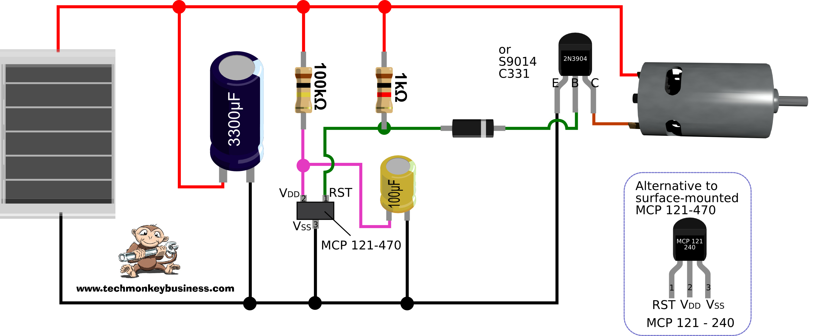
The circuit is very similar to the Miller Solar Engine except the output from the MCP 121 voltage supervisor requires a pull-up resistor where the 1381based Miller Solar Engine doesn’t. Things get a bit weird around the 100μF timing capacitor too.
You can find a copy of the MCP121 Series Voltage Supervisors Datasheet here: MCP_121_Voltage_Supervisor_datasheet.pdf
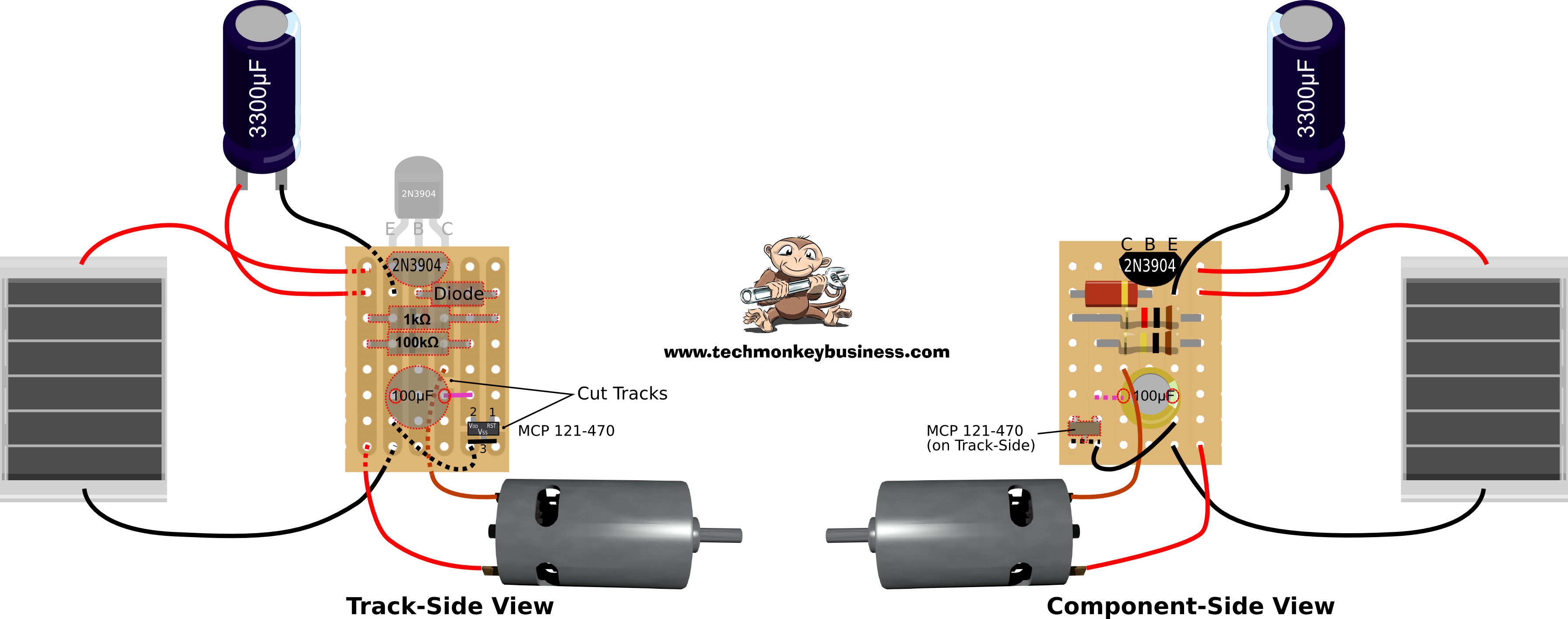
A Possible Layout
Most BEAMBot practitioners like to freeform their circuits rather than mount things on a board. I have never been very successful at this and had many BEAMbot projects spoiled by trying to track down dry-solder joints. This time I decided (after one failed attempt to freeform it) to build it on some strip board. The circuit layout above is the arrangement I used. Please note that the circuit is two sided. This allowed me to solder the surface mounted MCP121-470 directly onto the strips. I found this worked well. The tracks were cut in a couple of places as shown below.
If you have a a lower triggering voltage MCP 121-240 in a TO-92 package (looks like a transistor) you may be able to fit it to this layout. It will certainly be easier to work with than the surface mounted component.
How I Think it Works
Now I could be wrong on this so please don’t quote me on this.
The solar cell charges the main capacitor. Some of the charge slowly fills the 100μF capacitor through the 100kΩ resistor. The MCP 121 pin 2 monitors the voltage on the 100μF capacitor when it gets to 2.4V in the case of the MCP 121-240 or 4.7V in the case of the MCP 121-470 it closes the “drain” preventing current from flowing through from the RSP pin (or pin 1). The pull up 1kΩ resistor will now let the base pin of the 2N3904 transistor see the voltage on the main capacitor which will drive the pin HIGH and switch on the transistor. With the transistor turned on, the motor will run, discharging the main capacitor. The voltage at the MCP 121 voltage supervisor pin 2 slowly drops and so the MCP 121 will open it’s drain again. The open drain drags the voltage at the transistor base back down to LOW which turns off the transistor, stops the motor, and allows the system to recharge. I think I’ve got the HIGHs and LOWs around the right way.
The reason I am uncertain about how this works is that it was stumbled on by accident. I had set up the circuit very much like the Miller Solar Engine except with the pull up resistor on the MCP 121 output pin 1 (RST). This should have worked but it didn’t. Frustrated I decided to falsify the voltage being detected at the MCP121 pin 2 by using a voltage divider. This didn’t work. As I pulled out part of the divider it started working. At this point I just shrugged my shoulders and marked it down to luck rather than good design.
So here are some of my observations:
- Using the MCP 121–470 means the trigger voltage is higher. This means the system fires less often because it takes longer to charge up to the higher voltage, but it also means there is a higher voltage to dump through the motor and hence a higher torque possible. It also means that it is less effective in anything less than bright sunlight.
- Using the MCP 121-240 is easier because you are not dealing with a surface mounted component. The lower trigger voltage means less torque from the motor and so it can stall more easily. It is easier for the solar panel to achieve the lower trigger voltage and so the circuit fires more often and works in lower quality light levels.
- The diode may be superfluous. I initially put it in to try to raise the voltage on the 2N3904 base pin but it didn’t seem to make much of a difference and would continue operating quite happily with it bridged out with a bit of wire. So you’ll probably be able to leave it out.
- The size of the resistor and small capacitor have a big impact on how often and how long the motor runs for. A larger capacitor and/or larger resistor will lengthen the time between discharges and increase the amount of time the motor runs for. The values for these two components are not critical and you will find other combinations will work just as well if not better.
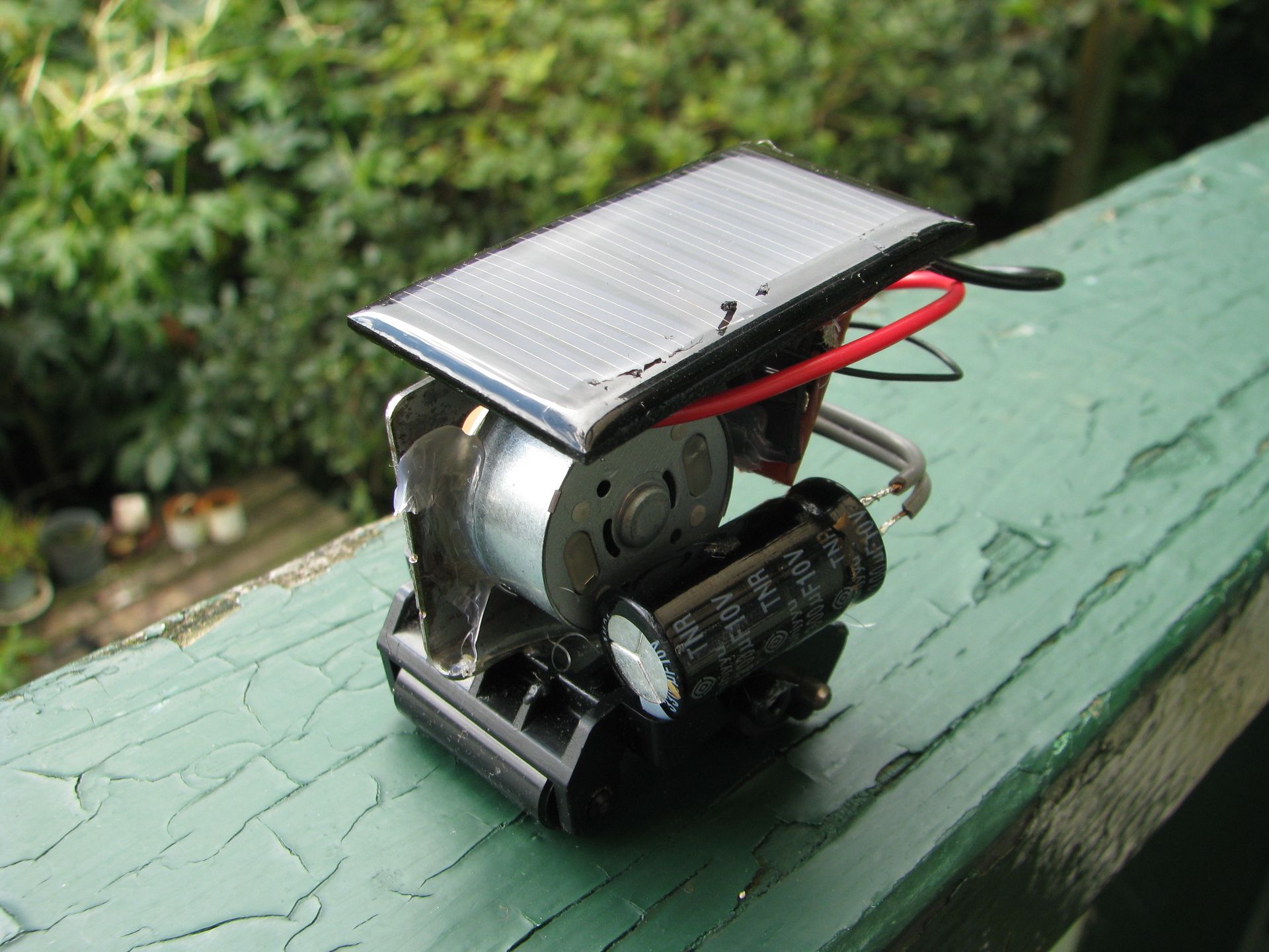
- Under good sunlight this BEAMbot runs about 10-20mm once every 5-6 seconds.
While the Miller Solar Engine was supposed to be super-efficient, I am less sure this one is. I suspect the continuous leakage through the pull-up resistor will significantly reduce its efficiency. Of course there are always the alternatives like the FLED and FRED solar engines which are simple to build and very effective.
Here are some links to other Solar Engines:
-
FLED Solar Engine - http://solarbotics.net/library/circuits/se_t1_fled.html
-
FLED Symet Project - http://bjcovertaction.weebly.com/jacksons-actions/symet
-
FRED Solar Engine - http://solarbotics.net/library/circuits/se_t1_fled.html
-
FRED Photopopper - http://raysbeambots.solarbotics.net/FLEDtutorial.htm
-
Miller Solar Engine - http://solarbotics.net/library/circuits/se_t1_mse.html
MCP Solar Engine in Action
Click on the image below to go through to youtube to see the Beambot doing its thing.
Good luck and feel free to correct me on the theory.