LED Array Dimmer Circuit

After moving into our new place in North Canterbury I was keen to make connections into the local community. I soon discovered the Amberley Tech Club which meet at the Hurunui Memorial Library in Amberley. One of their major projects was a book scanner for the local Leithfield Library which has a vast collection of historic books they were keen to digitise. The project was called the Bookomatic.
The Bookomatic consists of a holder for the books, a pair of cameras, and a Raspberry Pi. I was keen to add some lighting to the system to help get good, consistent illumination on the pages. Thinking about it further I realised that a dimmable LED array would be even better and allow the operator to set the lighting levels to suit the ambient lighting, the page colour, and minimise reflection. Of course, a power supply for this and the Raspberry Pi was also required. This project was the answer to this need.
There are a number of projects around the web that suggest using a resistor as a dimmer on LEDs. That works on an individual LED but for an array it is inefficient and poor practice. I will admit to creating a dimmer arrangement based on the LM317 adjustable regulator, but that too is a pretty awful hack. The best practice is to use Pulse Width Modulation (PWM) to dim the LED. To keep it simple, I made use of the super-reliable NE555 timer chip and used a potentiometer to vary the frequency settings for the NE555 chip.
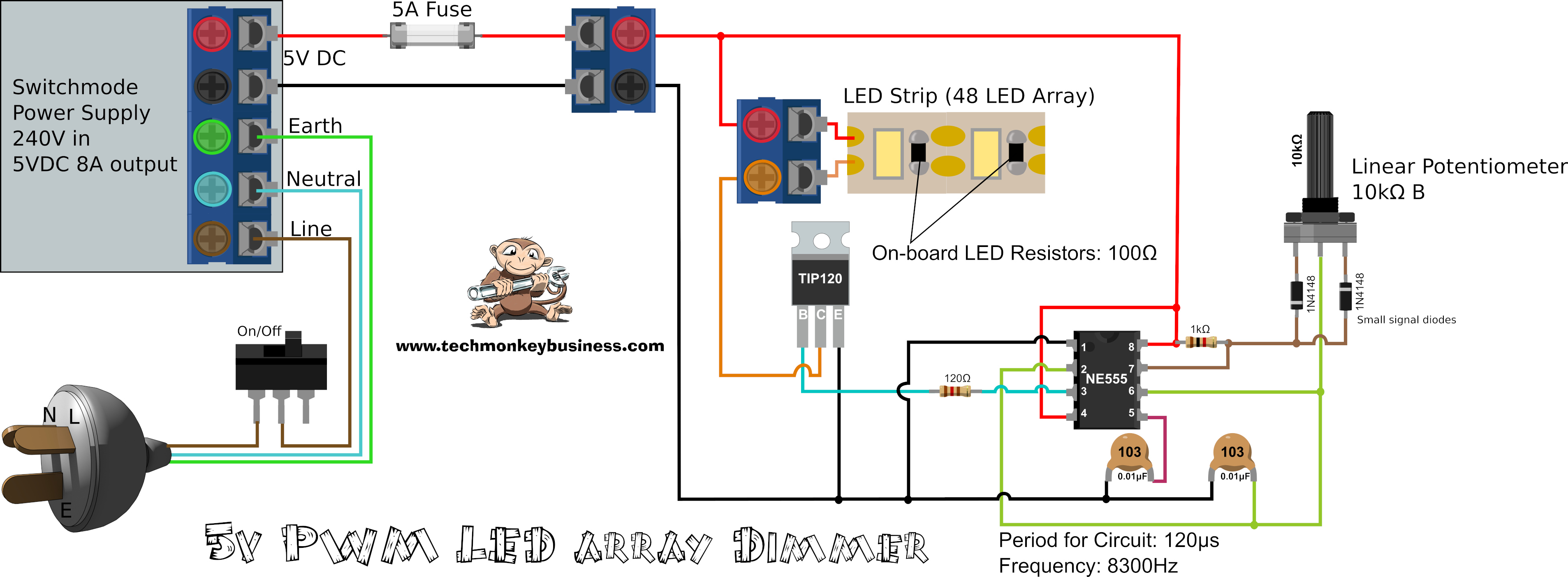
I found a number of circuits resembling the one below, but the resistance and capacitor settings around the NE555 gave very slow signals with periods of around 8 seconds which is clearly unsuitable for this application. I wanted something with a frequency of at least 120Hz or more to be beyond the human eye’s ability to detect flicker. In the end, I selected resistors and capacitors that gave a frequency of about 8300Hz. This gives a very smooth appearance to the dimness with no chance of any visual flicker being detected.
To keep things simple I chose to have a manual control in the form of a potentiometer rather than get the Raspberry Pi to control it. This meant it was intuitive and could be left set at a particular brightness or easily adjusted on a per page basis if needed.
The Circuit
This circuit shown is for the full system including the power supply and fuse.
Bill of materials
The components required are all commonly available and things like the Switchmode Power supply and strips of LEDs were easy to find on Aliexpress.
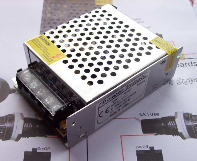
Power Supply: |
5V 8A Switchmode Power supply. Obviously this is only needed if you are making the dimmer as a stand alone system. |
Wall Plug and 240V cable: |
This was just recovered off some old defunct equipment. |
Switch: |
Single pole single throw switch rated for 240V and 5A. |
Fuse and holder: |
I chose a 5A fuse for this even though the power supply is capable of delivering 8A. This will help protect the Pi, tablet, and LED array. |
Screw Terminals: |
A couple of these for easy assembly. |
Timer Chip: |
NE555 timer chip. |
Transistor: |
TIP120 Darlington Transistor. Anything rated for the expected current of the LED array will suffice, but depending on the frequency of your PWM signal you may need to choose a fast switching one. It seems that the TIP120 is comfortable switching at the 120µs duty cycle my circuit operates at, but the frequency is probably getting a little too high. A heat-sink may be necessary. |
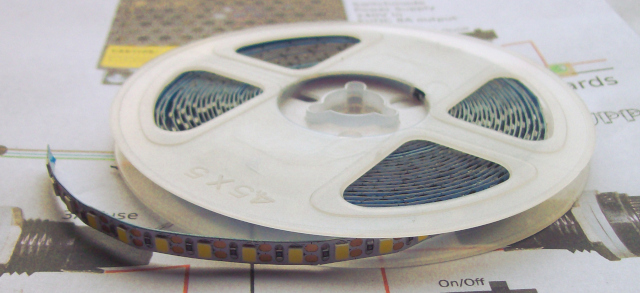
LEDs: |
The LEDs I used came on a 5m reel and were suited to 5V supply. The strip can be cut anywhere along its length and have wires soldered to it. Each LED has a matched resistor with it, so all that is required to run them is a 5V supply. |
Resistors: |
120Ω and 1kΩ. You may want to vary the 1kΩ resistor depending on what cycle frequency you want for the NE555. |
Capacitors: |
2 of 103 (0.01µF) ceramic disc capacitors. These are involved in the NE555 chip’s timing and so you may want to increase the capacitance of these to have a lower frequency from the NE555. |
Diodes: |
The diodes I used were recovered from old electronics boards. I don’t think there’s anything special about these diodes other than selecting signal diodes. The ones I used were both 1N4148 diodes. |
Potentiometer: |
This is used to vary the pulse widths. Something around the 10kΩ resistance works well, but make sure it’s a linear taper or Type B potentiometer. |
Switchmode Power Supply
The 5V 8A Switchmode Power supply is of the type used for home LED lighting systems. I purchased mine from the Vurum Store on Aliexpress. I have used a few around other projects and found them to be good robust supplies. In this project the 8A rated current gives us plenty of extra capacity for the Raspberry Pi and small tablet that will be running the Bookomatic’s cameras.
LEDs
The LED strip came from the Veromount Store on Aliexpress and were designed to take a 5V supply. With 5m worth on the reel, there are plenty of LEDs for other projects. They are quite bright, and will be well suited to the job.
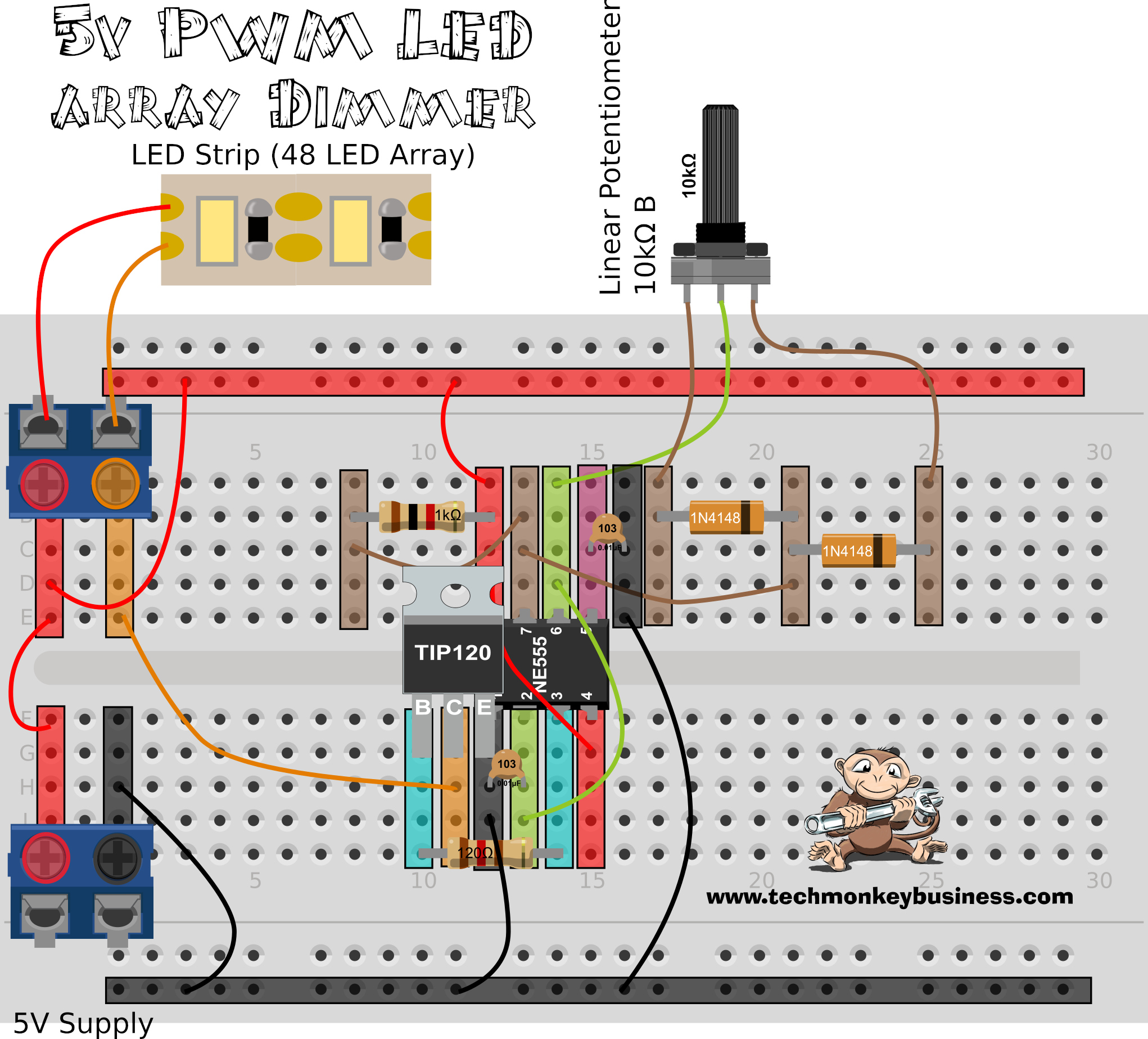
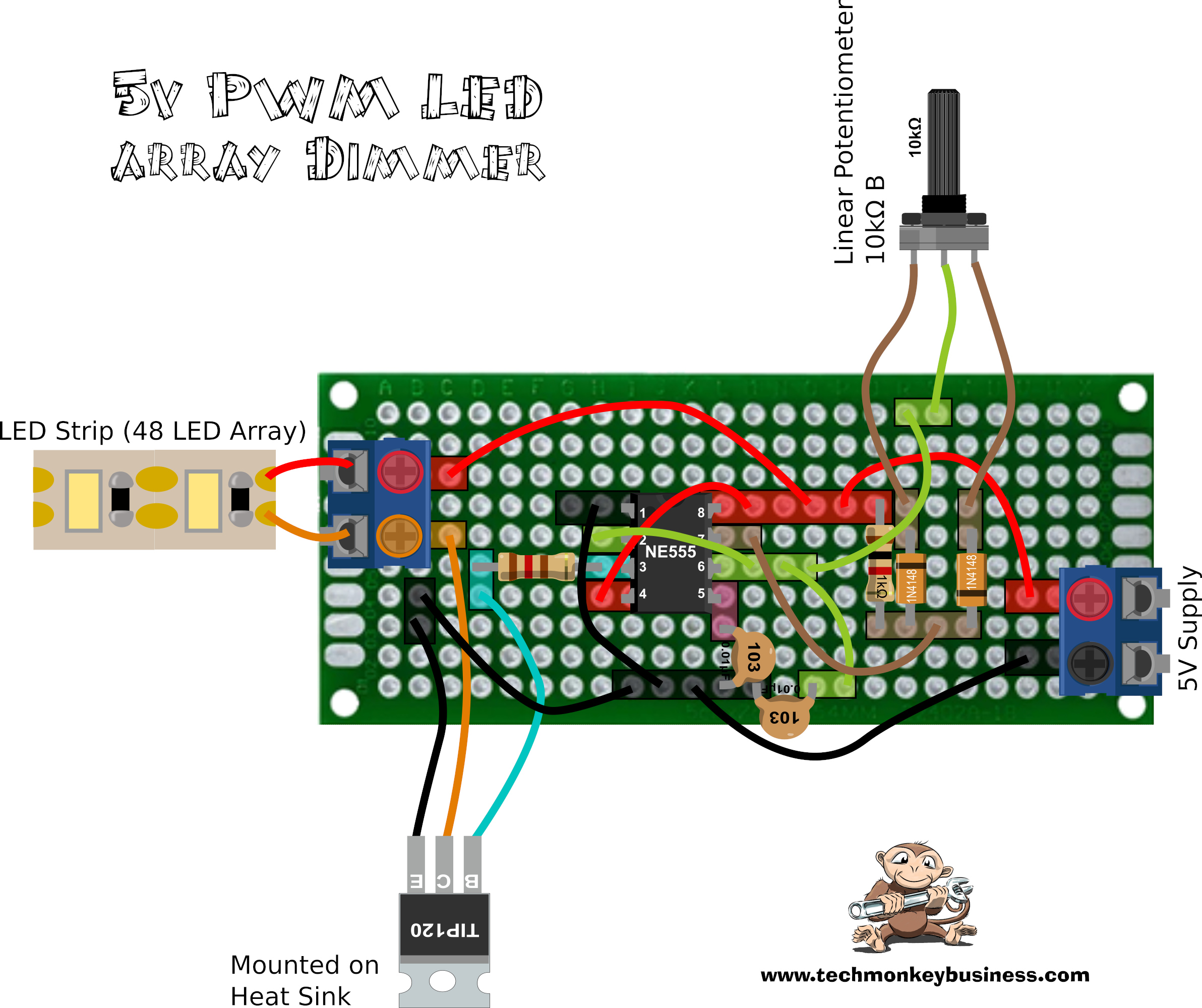
Physical Layout
Here are the physical layouts I used for the Bookomatic LED Dimmer circuits.
Breadboard layout
The coloured, semi-transparent bars show the connections within the breadboard.
Protoboard Layout
The coloured semi-transparent bars show where connections below the board need to be made.
Final Comments
The dimmer works well. Whether the frequency I have chosen causes problems in the long run remains to be seen. If the TIP120 gets too hot during extended operation, then I’d look at changing the capacitors to something a touch larger to reduce the NE555 cycle frequency.
Hopefully this project has some value for your own applications.


The described project is provided by Hamish Trolove under a Creative Commons Attribution-NonCommercial-ShareAlike 4.0 International License.