3D Model Contact Sheets using FreeCAD and ImageMagick
I’m sure I’m not the only person with access to a 3D printer who collects vast quantities of 3D printable models and then forgets which ones what and even that you had a particular model in your library. The best way I find to keep track of them is to have an image of each for quick reference. What I figured I needed was something to create a contact sheet with thumbnails of all the models in a chosen directory and the filenames of each.
While contracting at the additive manufacturing lab in the nearby research organisation we are also finding ourselves grappling with keeping track of the models customers give us and then matching their files back up with what comes out of the printer. Supposedly the 3D Systems 3dSprint software should put out a report with the model names, vital stats, and thumbnail for each printer build. It produces a report but the thumbnails are absent and we can’t find where they went or even if the program generated them in the first instance.
So with two useful applications of a contact sheet of 3D models for printing I decided to hunt around and see what would do the job. There are several commercial products, but that seemed a little excessive for what I wanted to do. My first thought was MeshLab but I couldn’t find any information on how to get it to render when using the Meshlabserver commandline application and besides it couldn’t handle .STEP files which were commonly used in the additive manufacturing lab. In the end I felt a FreeCAD/ImageMagick combo would be the best tools for the task.
Because FreeCAD scripting is in Python this made it easy for me to come up with a script that included a simple interface and could call on ImageMagick to generate the contact sheet once the model images were rendered. It also allowed me to work through nested directories of models if that was required.
Prerequisites
Obviously you need FreeCAD and ImageMagick installed in order for this to work.
I initially designed this script for the FreeCAD 0.17 and ImageMagick v6 on this NetrunnerOS Linux machine, but because I wanted to use it for where I’m contracting I needed to make something that would work on lesser operating systems such as Windoze which would be running the latest version of FreeCAD and Imagemagick. This created three problems; ImageMagick’s commands have changed in a small way between version 6 and version 7 and the tkinter I was relying on varies between the Python 2.8 in FreeCAD 0.17 and Python 3.6 that ships with FreeCAD 0.18. To my annoyance I found that the tkinter that ships with the Windoze versions of FreeCAD is broken which necessitated using Qt for the interface.
So what we ended up with was a selection of scripts that are suited to the different editions of FreeCAD and ImageMagick, and the different operating systems. I suspect Apple Macs will probably work with anything that works for Linux. For the sake of history I have included the tkinter-based versions as well.
The Macros
Below are links to the various different flavours of this script.
Linux Versions:
FreeCAD 0.17 and FreeCAD 0.18 with ImageMagick V7
FreeCAD 0.17 and FreeCAD 0.18 with ImageMagick V6
Linux Versions using tkinter:
FreeCAD 0.17 with ImageMagick V6
FreeCAD 0.17 with ImageMagick V7
FreeCAD 0.18 with ImageMagick V6
FreeCAD 0.18 with ImageMagick V7
Windoze Versions:
FreeCAD 0.17 and FreeCAD 0.18 with ImageMagick V7
FreeCAD 0.17 and FreeCAD 0.18 with ImageMagick V6
Using the Macros
Once you have selected the appropriate Macro, drop it into a directory you can access with FreeCAD or use the default directory FreeCAD uses to store macros.
- Start FreeCAD
- Go to the top bar menu item “Macro” and select “Macros” from the drop-down.
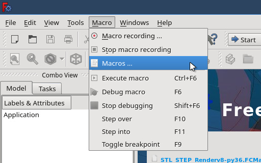
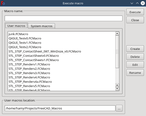
This will open a macros dialog where you can select the macros you want to run. In the bottom of this window there is a field to select the directory where you have put the macro. Select the Macros you want to run and click on the “Execute” button in the top right of the Macros dialog.
You will be presented with an interface that looks like this;
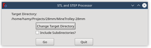
- Hit the “Change Target Button” and use the popup file navigator to find the directory full of models you wish to process.
Depending on the directory structure you wish to process you can check or uncheck the “Include Subdirectories?” check box. If you have checked it, the macros will go through all of the subdirectories of the directory you have chosen and process every .STL or .STEP file it comes across. If left unchecked, the macros will only look at the models in the target directory and exclude any in the subdirectories.
When you are ready hit the “Go” button. Depending on the speed of your machine and complexity of the models, rendering and processing the images may take a little while. On Linux machines you will see the models opened, rendered, and the model closed again. On Windoze machines you will see nothing happening.
Once it has rendered the models, it will invoke ImageMagick to produce the contact sheet. A message window will popup to tell you it has completed the process.
If you are processing a directory with a number of subdirectories with models, all rendered model images will appear in the base level of the target directory rather than being scattered throughout the directory structure. The contact sheet will also appear here. The contact sheet is named with a prefix of “1-” and the name of the target directory. One possible challenge is that the script does not recognise multiple models with the same name in a directory structure and will over-write the previously rendered model image. If you have a file naming standard where you name everything the same, then you may find the contact sheet is a little thin on rendered images.
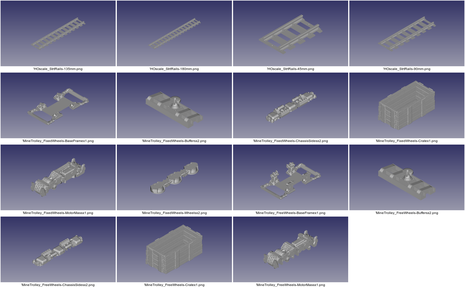
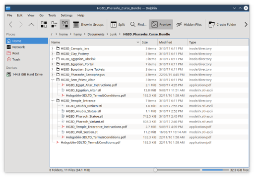
Here is a demonstration of the script in action on a directory structure produced by unzipping the very cool Hobgoblin3D Pharaohs Curse Bundle Pack. As you can see the file contains a number of nicely set out directories with .stl files in them.
In FreeCAD we execute the macro.
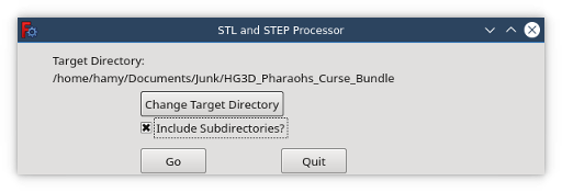
Select the directory, and check the checkbox to include all the subdirectories. We then hit the “Go” button. After a bit of processing time we end up with a target directory full of rendered images and the contact sheet.
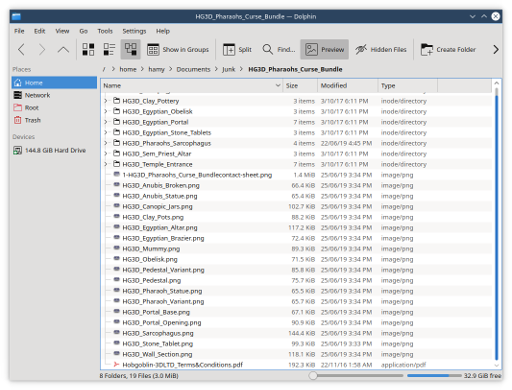
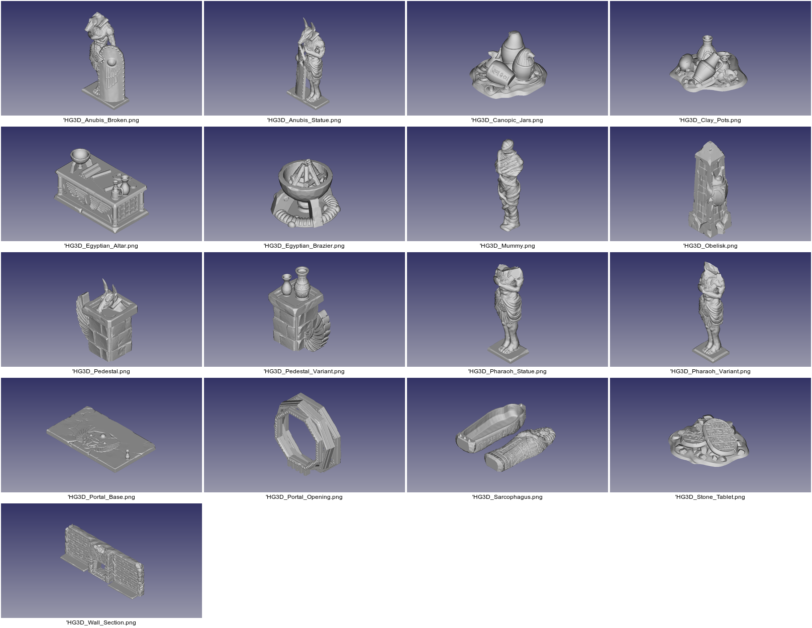
The contact sheet produced is called “1-HG3D_Pharaohs_Curse_Bundlecontact-sheet.png” and looks like this:
Quirks of the Windoze Versions
I tried out the script developed for Linux on a Windows 7 machine running FreeCAD 0.18 and ImageMagick V7 and it worked OK, except for the “Done!” message window appearing underneath the macros interface. This meant it was impossible to acknowledge it and continue working. Really dumb! So I had to adjust the script so the macros interface did not remain on top all the time. Unfortunately this means it has a habit of hiding behind the FreeCAD interface. You may need reveal it by clicking on its tab thing in the Windoze bottom bar. Unfortunately there’s not much I can do about that.
I tried the script on another Windoze machine with FreeCAD 0.18 and ImageMagick V7 installed from the same installers. On this machine FreeCAD ran the script and sat there for a while rendering away producing a bunch of blank images from which ImageMagick tidily constructed a contact sheet entirely populated by blank images with their filename. I can only presume this was something like Windows 8 or 9 and the FreeCAD save snapshot image process doesn’t work properly on it. Unfortunately there’s nothing I can do about that. Maybe greater minds will be able to take this script and adjust it to work better on Windows Machines.
Extending the Functionality
If you want to add other 3D model formats that FreeCAD can handle then look for the two lines looking like this;
if (item.rsplit(".", 1)[1].lower() == "stl" or item.rsplit(".", 1)[1].lower() == "step"):
and change the suffixes or add another bit on the end to include your desired format. For instance if you wanted to include .obj files then your code would have this;
if (item.rsplit(".", 1)[1].lower() == "stl" or item.rsplit(".", 1)[1].lower() == "step" or item.rsplit(".", 1)[1].lower() == "obj"):
Tweaking the Look of the Contact Sheet
You may wish to change the background of the contact sheet or the number of thumbnails across. These are all things you can do with the command to invoke ImageMagick’s montage process.
In the ImageMagick V7 versions of the script the line to look for is;
BaseComm = [
        "magick","montage","-verbose","-label","'%f","-font","Arial","-pointsize","12",
        "-background","transparent","-fill","black","-define","jpeg:size=400x",
        "-geometry","400x+2+2","-tile","4x","-auto-orient",
    ]
For the ImageMagick V6 versions the line is the same except doesn’t have the “magick” word.
BaseComm = [
        "montage","-verbose","-label","'%f","-font","Arial","-pointsize","12",
        "-background","transparent","-fill","black","-define","jpeg:size=400x",
        "-geometry","400x+2+2","-tile","4x","-auto-orient",
    ]
Picking this apart here are what each of the bits mean and some thoughts on what you might do to modify them.
| magick | Only required for ImageMagick V7 |
|---|---|
| montage | |
| -verbose | Report the process so that the user knows something is happening |
| -label | Include a label for each image. What the label contains is the next item in the list |
| %f | Include the filename in the label. Other options include; %d the directory, %h image height in pixels, %w image width in pixels. |
| -font | Specifies a font for the label |
| Arial | Name of the font |
| -pointsize | |
| 12 | Size of the font |
| -background | option to define the colour of the background |
| transparent | Specified colour for background. You can also use definitions like “black” or “#FFFFFF” for white. |
| -fill | Fill around the images. This is not so relevant when all the iages are the same size and the thumbnail geometry matches the tile geometry as it does in this case. |
| black | Fill colour |
| -define | This is the geometry of the thumbnail |
| jpeg:size=400x | In this case it is 400 pixel wide and free to be any size tall. 400X400 would restrain it to being within 400 pixels vertically and horizontally |
| -geometry | This is the geometry of the space allocated to each thumbnail. |
| 400x+2+2 | In this case it is sized to fit the thumbnail exactly and have 2 pixels clear around each thumbnail. |
| -tile | This defines how many thumbnails to have across the contact sheet produced |
| 4x | In this case 4 thumbnails across, but it could be constained to six thumbnails tall with “x6” for example. If undefined ImageMagick will try to produce a spread as close to square as possible. |
| -auto-orient |
I think that about covers it. The coding is a little rough but it does the job.