FrankenVinci - Converting a Bricked Da Vinci to RAMPS Controller

OK, so you have bricked your XYZ Printing Da Vinci 3D printer. Don’t be down-hearted. Rejoice! Now you have a chance to turn it into something much more versatile. You can also download this guide as a pdf if you would prefer:

Recently I started a contract at [undisclosed business] looking after their STEMM developments. One of the things I had to deal with was looking after their not inconsiderable fleet of 3D Printers. In amongst them were two XYZ Printing Da Vinci printers they were coaxed into buying. The Da Vinci 3D Printers are a good solid frame with some nice componentry but their electronics, software, and filament supply model are truly awful. If XYZ Printing were wiser they would open up their model to allow the use of any filament and encourage hardware hacking – they would sell more of their equipment, and also engender a more positive culture amongst their users.
Anyway, with reference to the great work by SteelCityElectronics on the Da Vinci extruder thermistors, the printer bed thermistors and Ginge’s fantastic Marlin Builder website, I was able to refit a standard Da Vinci 1 3D Printer with a RAMPS board and Arduino Mega microcontroller to produce a good solid 3D Printer that can run on any of the open source software typically used for 3D Printers, and any filament.
This is not a step by step guide but hopefully will have enough information and provide enough detail and code for anyone else who may have ended up with a bricked Da Vinci that is out of it’s warrantee period to be able to reproduce these results and get themselves a working printer again. This is not a quick fix, this is major surgery, and the name “FrankenVinci” pretty much conveys what you end up with. You can expect to take a day or so to do this. However, by using this guide I hope I can save you a heap of time. Once you have completed the fix, it will open up the potential for much better control of your printer and greater functionality. You will also get a functioning printer back that may otherwise have been consigned to an e-waste service or at worst landfill.
At the end of this fixing process the Da Vinci printer will be fitted with a RAMPS board and Arduino Mega microcontroller. It will be able to run all of the common Reprap software such as Cura, Repetier, ReplicatorG, Printrun/Pronterface/Slic3r, and take as wide a range of model formats as are currently available. It will also be able to run any 1.75mm filament including PLA, ABS, and any of the more challenging filaments simply because it allows you direct control of all of the heated parts. Finally, it won’t hassle you about upgrading to the latest version, (Well actually Cura will, but that’s not going to screw up your machine if you do upgrade). Having forced air cooling, I suspect the motherboard and associated drivers are less likely to cook than on the original Da Vinci motherboard. All in all it is an upgrade.
The Da Vinci in Surgery
What was done
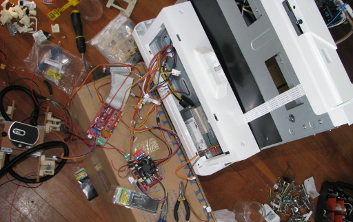
After you have pulled off the side panels (they unclip from the top), the very first thing to do is to take note of what connects to what. The image below shows the connections to the original Da Vinci motherboard. The photo has been stitched together from several photos so there are a few wonky places in it.
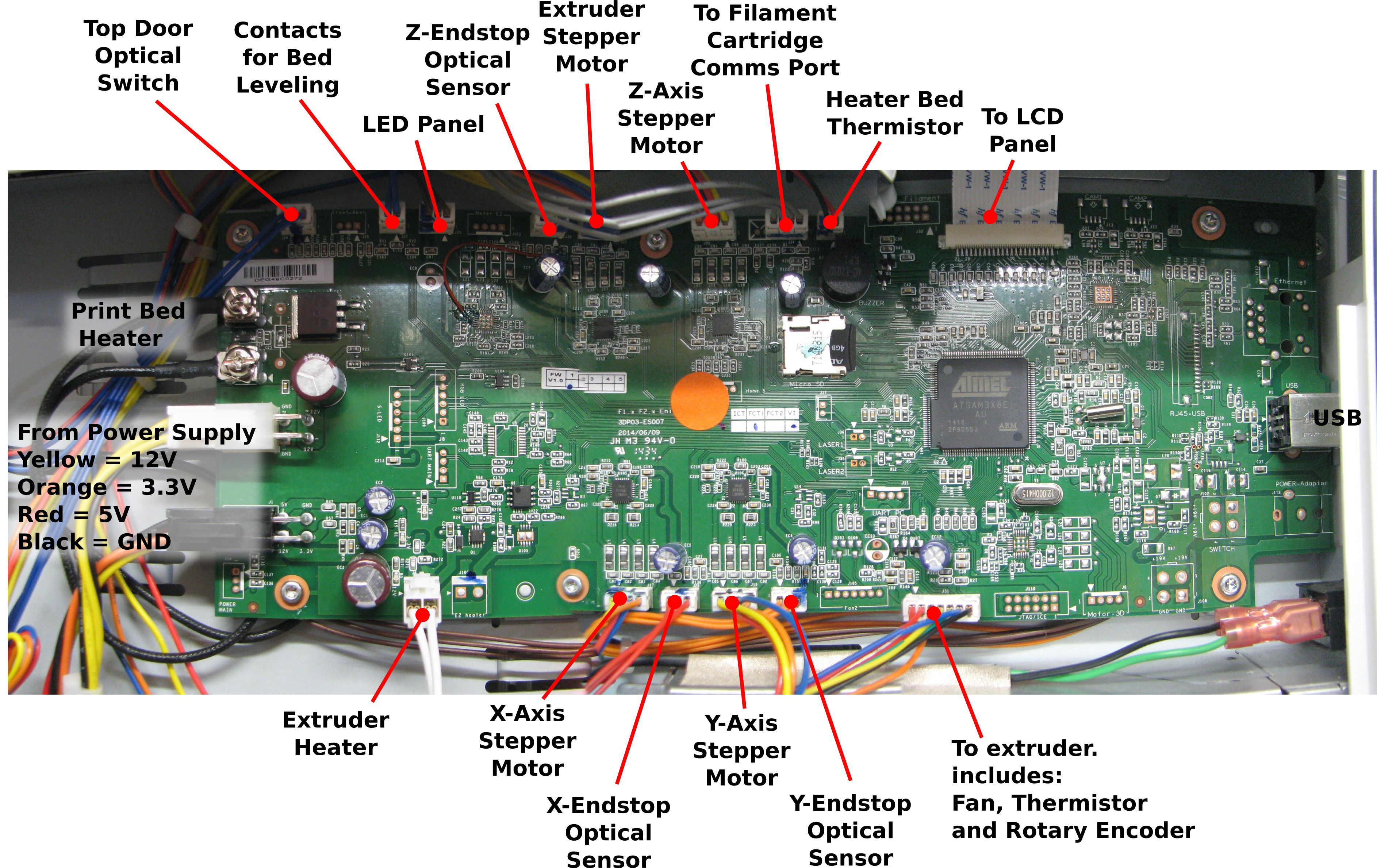
Click on the image for a hi-res version.
Remove the Da Vinci control board and as you do so label what bits of hardware the various bundles of wire connect. Ultimately some of them will not be needed at all and can be completely removed. The FrankenVinci uses mechanical endstops instead of the original optical endstops and so these can be removed permanently as can the connection to the cartridge, the LCD, and LED strip, and the bed leveling contacts.
Connections to the RAMPS
Supply:
Only the 12V and Gnd connections are required. I snipped the wires off the plug with the two yellow 12V wires and two black ground wires and connected them to the supply block.
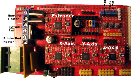
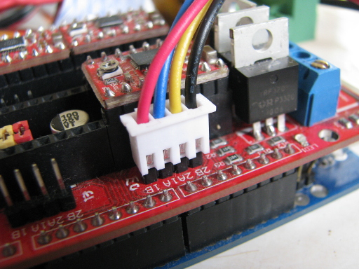
Heaters:
Bed heater (black wires) had some almost convenient terminals on them. I crushed these into a metal tabs that could insert into the screw terminals for RAMPS port D08.
The extruder heater wires (white) had their connector snipped and the wires extended with 7.5A wire, then connected into the RAMPS port D10.
Fans:
The extruder fan was supplied from RAMPS port D09 (where the extruder heater and bed header connections are.) I ran a new pair of wires up to the heater head and connected into the fan wires there. In hind sight I would have used the existing wire bundle shared with the extruder thermistor and filament counter device but at that time I had not quite traced out what was happening in the extruder head with the little circuit board that the bundle connects to. In the original seven wire connector, the fan wires are the green and the yellow ones (I think).
The additional fan blowing over the RAMPS board components was simple connected into the 12V supply port so it would turn on as soon as the printer was turned on. The fan itself was a repurposed 12V 50mm diameter CPU fan. The 3D printed holder for this was based on Schlotzz - “RAMPS 1.4 Fan Mount, 40mm, parametrizable” . The Blender File and STLs can be downloaded here: STLs, Blender files.
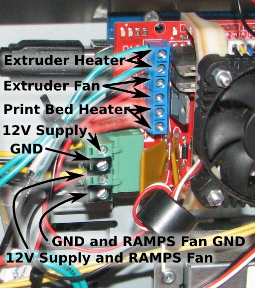
Supply, Fan, and Heater Connections to RAMPS.
Stepper motors:
The original plugs pin spacings were too small to be used directly with the RAMPS board and so I needed to come up with an alternative plug that would fit the RAMPS headers (standard 2.5mm pin spacing). Because I had a bunch of them and I knew they worked well for connecting stepper motors to RAMPS boards (Camera Slide Project), I used 3S Lipo battery balance plug extensions. These can be purchased from Banggood or Hobbyking. The downside of this is that the colours don’t match if you want to keep the stepper motor coil connections correct. I clipped off the original plug connector and soldered the balance cable extensions in their place. The wire connections are:
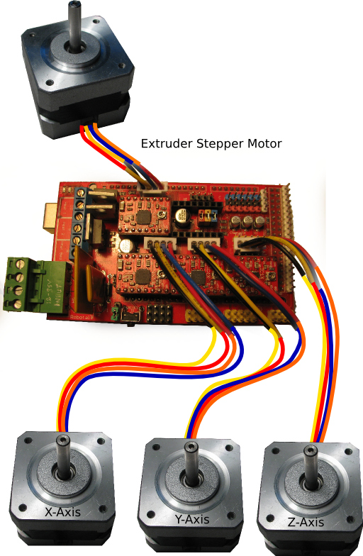
RAMPS to Da Vinci Stepper Motor Connections using 3S LiPo Battery Balance Wire Extentions
| Da Vinci stepper motor leads | 3S balance plug leads | RAMPS board stepper coil name |
|---|---|---|
| Yellow | Black | 2B |
| Red | Yellow | 2A |
| Blue | Blue | 1B |
| Orange | Red | 1A |
3S LiPo battery balance port connector used to connect motor to RAMPS Board.
In addition to connecting the motors to the RAMPS board you will also need to install the Pololu Stepper Motor drivers. Situated under each driver position is a set of jumper pins. You will need to put jumpers of all of them for all of the stepper motors you will be using.
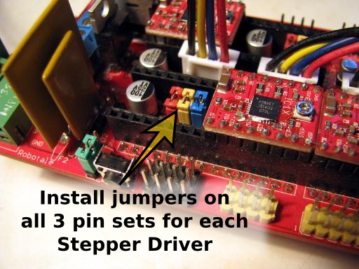
Pololu Stepper Driver Jumpers.
The orientation of the stepper driver board is shown below.
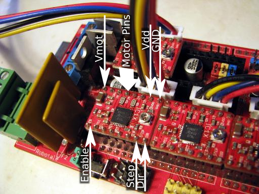
Pololu Stepper Driver Board Orientation.
The Pololu Stepper Drivers used in the illustrations above are from the Camera-slide project rather than this project and so don’t have the heat sinks attached, but it would be wise to use the heat sinks on the 3d printer drivers.
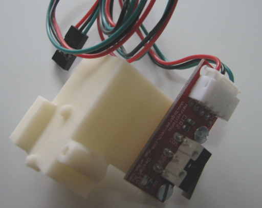
Endstops:
For reasons of reliability, the optical end stops were swapped for mechanical endstops. These were purchased from Banggood and come complete with a nifty board, and connection leads that are compatible with a RAMPS board. Each of these needed a new holder to position them correctly. The files for these are linked from my website: STLs and Blender files.
The endstops are connected to the RAMPS board as shown below.
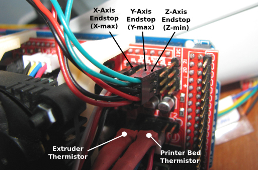
It is important to note that the X and Y axis endstops are connected to the maximum connectors on the RAMPs and the Z – axis endstop connects to the Z-minimum port.
Update: 14th August 2017: I have been contacted by a number of people following this guide as they rejig their Da Vinci printers. The common question is, “Have you got any photos of the end stops in place?” A very fair question and made me wonder why I didn’t include them in the first instance. So here are some photos of the end stops in their final locations. The philosophy I used was that I would match the locations of the original sensors as best I could allowing for the fact that the original sensors were optical and I was using mechanical switches. Hopefully these photos will be clear enough. Because the project was carried out for someone else, I no longer have the printer available to take more shots. Please excuse the background mess in these shots.
Click on the image for a high-res version.
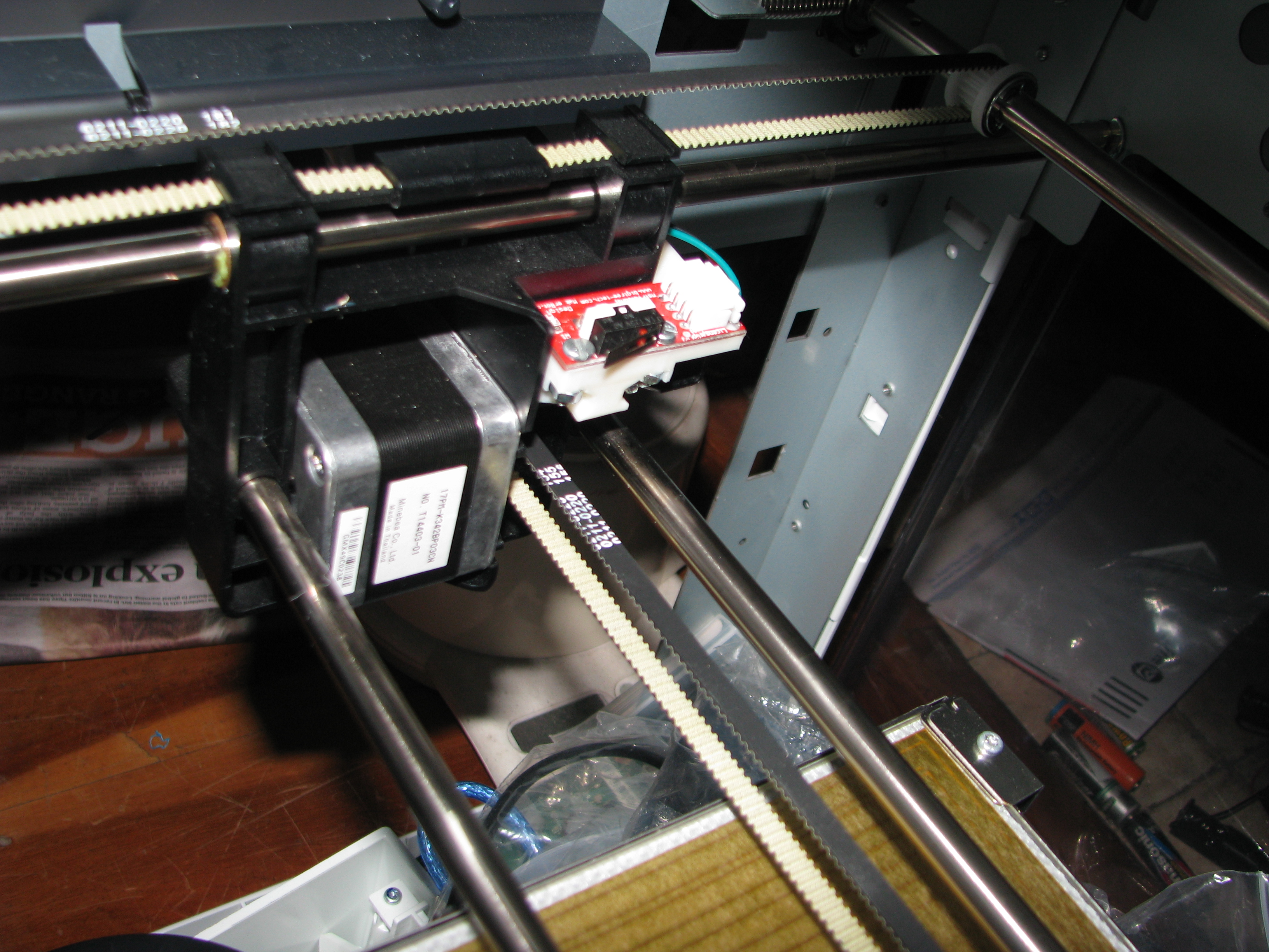
Click on the image for a high-res version.
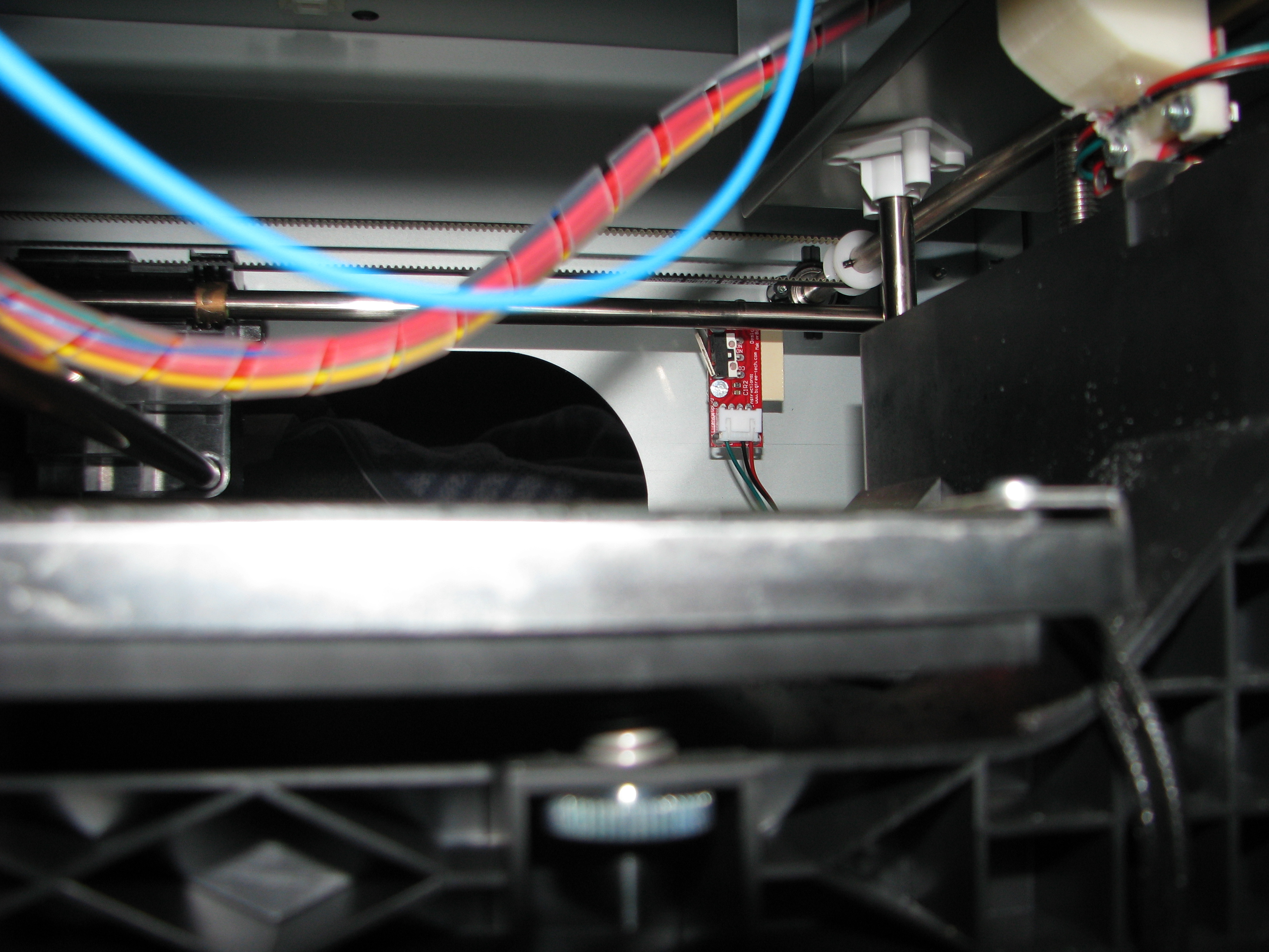
Click on the image for a high-res version.
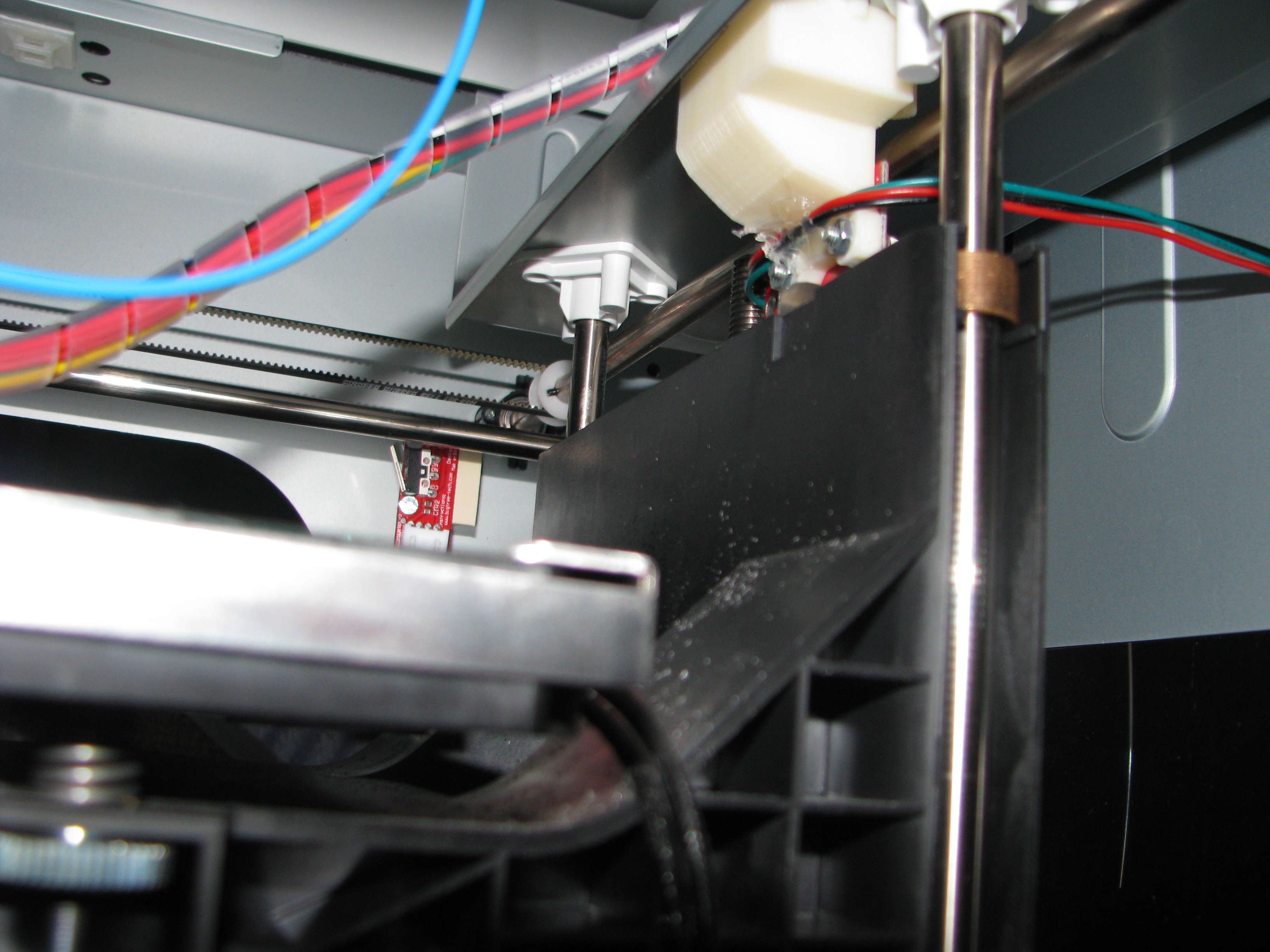
Click on the image for a high-res version.
Thermistors:
The thermistors connect to the RAMPS board as shown in the previous image. If you are looking to use the original 7-wire connector to the extruder head (I wish I had done so in hindsight), then the extruder thermistor connections are the orange and black wires.
Thanks to the work of SteelCityElectronics I was able to approximate the Da Vinci extruder type with a 100kΩ NTC and a beta value of around 4380K. Having said that, I created a thermistor table for this, but found that using the type 5 thermistor (ATC Semitec 104GT-2 with 4.7kΩ pullup) in the firmware configuration file, worked better.
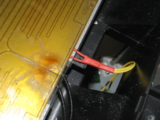
The printer bed thermistor was a very weird one which I didn’t trust much so I removed it and replaced it with a 100kΩ NTC thermistor with a beta value of 3974K. This is one that is commonly used on Repraps, and in the firmware configuration file is the type 7 thermistor (Honeywell 135-104LAG-J01 with a 4.7kΩ pullup). This thermistor is somewhat larger than the original one and required a quick bit of work with a craft knife to cut through the insulating mat (to avoid kicking up mineral fibres don’t cut this with a rotary tool) and a rotary tool to cut a small socket into the bed support plate. The downside is that the larger thermistor also measures some temperature midway between the bed temperature and the temperature of the supporting frame which means that if you are reading 70°C the bed’s actual temperature will be up around 110°C. I may add some more insulation under the thermistor to try to get this closer to the bed temperature.
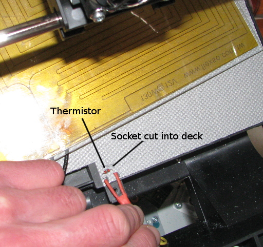
Installing the thermistor in the printer bed.
USB:
The USB connection is through the Arduino Mega. I found Banggood supplied an appropriate USB type B plug and socket extention. The bonus was the socket was designed to be panel mounted and so could be neatly fitted into the USB opening vacated by the old Da Vinci motherboard.
The Firmware
I used Ginge’s brilliant Marlin firmware builder as a first pass at generating the Firmware for the FrankenVinci. I then worked through it carefully comparing what hardware I had to what the generated firmware thought I had. There were a lot of changes necessary, and some of them I carried across from the Da Vinci / RAMPS firmware described by thermo269.
Here is a rough and not-at-all-complete rundown of the changes made to the firmware to suit the configuration of the FrankenVinci.
Baud rate: Reduced to 115200
Thermistors: Extruder - Type 5, Printer bed - Type 7.
End stops: Only the three end stops were used – X-max, Y-max, and Z-min
Home directions: X = 1, Y = 1, Z = -1
Print area dimensions:
#define X_MIN_POS -33  //DaVinci Version calls for -33
#define Y_MIN_POS 0	//DaVinci Version calls for -12
#define Z_MIN_POS 0
#define X_MAX_POS 237  //Using Da Vinci Version
#define Y_MAX_POS 217  //Using Da Vinci Version
#define Z_MAX_POS 202
Travel speeds:
#define NUM_AXIS 4 // The axis order in all axis related arrays is X, Y, Z, E

#define HOMING_FEEDRATE {50*60, 50*60, 4*60, 0}      // set the homing speeds (mm/min)

#define DEFAULT_AXIS_STEPS_PER_UNIT {80.00, 80.00, 2560.00, 89}
#define DEFAULT_MAX_FEEDRATE {200, 200, 8, 50}      // (mm/sec)
#define DEFAULT_MAX_ACCELERATION {1000, 1000, 100, 5000}
The FrankenVinci Firmware can be downloaded from here: FrankenVinci Marlin Firmware
You will need the Arduino IDE to load it. I used Arduino1.6.8 to develop this.
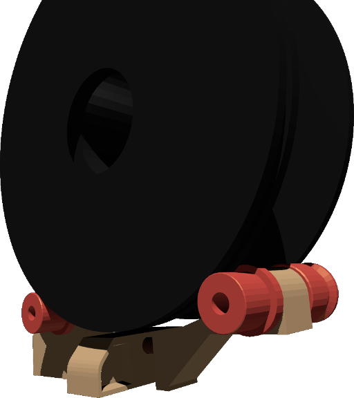
The filament holder
Having done away with the standard Da Vinci proprietary ABS filament cartridge we are left with a large slot into which a regular filament spool will fit. To help keep the filament unwinding smoothly I quickly designed up a spool holder to drop into the space. It is not a brilliant design and there are a few spots were my measurements were a bit off, but it is at least a starting point for better holders.
The STLs for this can be downloaded from here: STLs
and the Blender files used to design it can be found here: Blender Files.
It is designed to use four 608z skate bearings, Ø8mm diameter axles, and an Ø8mm dowel down through the centre to hold it together. The rollers are designed to be held onto the axles with an embedded Ø3mmNB nut and M3 grub screws or short lengths of M3 threaded rod.
What you need to chop up or remove
As much as possible I tried to leave the main structure alone and so there is very little that needs to be cut. The only panel bashing that occurred was the removal of a web from within the cartridge slot. The particular web is the one that runs down the centre of the back panel and helps keep the cartridge in place. This can be removed with a sturdy craft knife, and a file. The other bit requiring cutting was a hole in the plate that covers the control board area. Now that we have the cooling fan for the RAMPS we need to get some air through it, so you will need to cut a hole in the back panel. A drill, and coping saw will make short work of this.
The other changes are removal of the things that are no longer needed. The Da Vinci is quite well designed for accessibility and so once you find the various clips, all the panels come off quite easily. This will allow you to get access to the LCD screen, the LED strip light board. These can both be removed. I deliberately removed the LCD to stop people thinking that it would have anything useful displayed there while it was running. At some stage I will cover the holes left.
You can also remove the cartridge connector board, the wires running from the metal strips around the heated printer bed periphery. These were for the Da Vinci’s awfully ineffective bed height calibration system which we are happily doing away with. Other than the various optical end stops and associated wiring and mounts the only other major item to come out is the Nozzle wiper and its tray. Getting rid of this early will help give you good access to the interior of the printer. This is a simple matter of removing a couple of screws.
Setting up the software
The software settings still need a bit of tweaking, but here are the settings I have used in Cura to achieve successful prints. These are illustrated in more detail in the “User manual”.
The machine settings in Cura are;
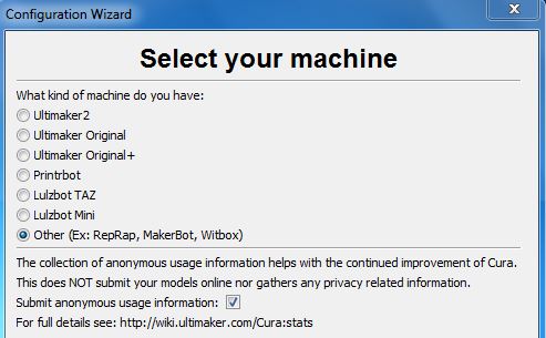
When you first start Cura it will ask you to set up the 3D printer profile.
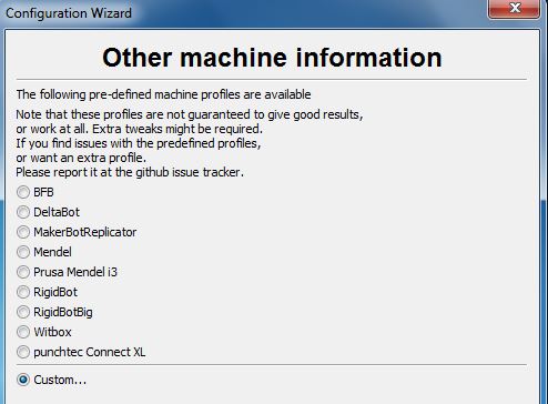
Refer the the Cura website for detailed instructions on the use of Cura and its configuration. Here are a few direct comments to help get your FrankenVinci underway efficiently. The following are snapshots from the Cura Startup wizard with the appropriate values shown.
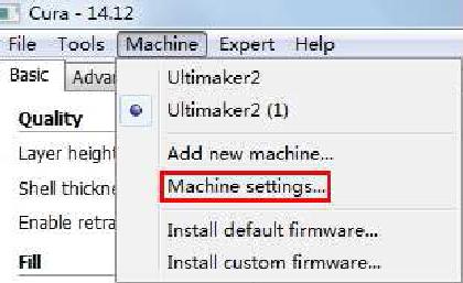
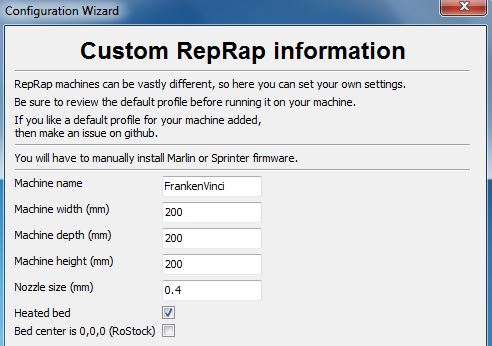
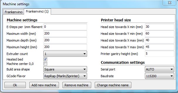
The machine settings screen can be update:d at any time and allows you to use different machines. The Machines drop-down in the tool bar will allow you to select between the FrankenVinci and any other printers you may happen to run with the same interface.
In the Machines Setting screen the E-Steps per 1mm filament has been left a “0” because this will allow the software to leave it to the firmware to determine the appropriate federate.
When running the Cura getting started Wizard, it may ask whether you want to upgrade the 3D Printer’s firmware. The correct answer is “No”. The firmware has been specially tailored for making use of the Da Vinci hardware and modified endstops. If you accidentally load the new firmware, you will need to reload it.
- Filament diameter = 1.75mm
- Nozzle diameter = 0.4mm.
- Print volume dimensions: 200mm x 200mm x 200mm
- Maximum print speed: 150mm/sec
- Baudrate: 115200
For a coarse-ish print I would suggest the following settings in the interface:
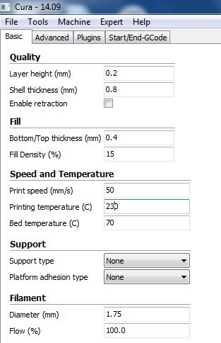
In the Advanced tab there is a setting for the initial layer thickness. You may need to play around with this to get your prints to stick reliably and yet not get some much material dumped down that it catches on the extruder head and gets pulled up again. Unfortunately I have yet to get a good feel for this setting and so can’t make a recommendation other than start with the “0” setting which leaves it to the firmware to determine.
Installing Printrun/Pronterface
Printrun/Pronterface is a zipped up archive of the Windows Binaries with all of the necessary dependencies including the Slic3r software for converting models into gcode for the printer. To install, just find a place on your computer where you want to put it and unzip the archive into that location.
The Pronterface interface looks like this:

To reiterate: the printer bed temperature sensor under-reads by quite a margin. For an ABS print, a setting of 70°C in software was enough to get at least 110°C on the printer bed. I feel I still have some refinement and improvements to do in this area.
Unfortunately, getting prints to stick is still a challenge with the FrankenVinci (at least with ABS anyway), but this is a matter of getting to know the printer and refining the settings and using appropriate materials and methods on the printer bed to improve the chances of your prints sticking.
Trouble shooting
Stepper Motors and Not Talking
I lost a lot of time trying to get the stepper motors to run. I eventually tracked it down to a bad connection between the RAMPS and the Arduino Mega. What was happening was the solder tabs under the high current connector port from the power supply, were too long. They were pressing on the Arduino Mega’s 12v power supply port and propping the two boards apart a small amount. This was enough to prevent the pins for the stepper control pins from connecting. By filing down the tabs, the two boards sat flush together and the problem was solved.
BaudRate
Initially I tried to use the higher baud rate common for Marlin, but filed to get anything useful to come through the link. When I slowed it down in the firmware and the interfaces, the problem went away. So if you are having problems with the computer not talking to the Arduino, try a different baud rate. The firmware is set for 115200.
Of course there are a heap of things that I could describe here, but I recommend you use good fault finding technique, a voltmeter, an ability to substitute components, and your good logic to figure it out. More often than not, it will be a poor connection, and so be prepared to unsolder some of your joints and re-solder them. Have a look at the various Reprap forums. There are some good solutions and some bad solutions. Just ignore the bad ones.
General guidance for using the FrankenVinci
I wrote a guide for using the FrankenVinci. Have a look at this for more information on running your FrankenVinci.
What I Could have Done Better
The z-axis endstop position is a touch higher than it needs to be. By lowering it by 3 – 5mm it will give some more adjustment room on the printer bed leveling screws. A simple alternative is to put a couple of washers under the metal blade that presses on the Z-axis end stop. This “blade” is mounted on the printer bed support frame and held down by a single screw.
The z-axis does not step back much after it has homed. This is not a problem, but it might be useful to increase this. This is defined in the firmware and would require an update:d issue of the firmware.
Yayy! That’s it!
You have taken a step into a wider world of 3D printing. Congratulations.
Final note:
Your Da Vinci printer was already stuffed before you started and so at least we can’t make it worse. This information is provided with the best intentions, but at your own risk. I cannot offer any assistance or problem solving and would suggest you look at the various (and quite helpful) forums on Repraps and Da Vincis to help you resolve whatever has you stumped – after all this is what I did and believe me it did take some time. Most important of all, be prepared to call on your abilities to think about that you are seeing and figure out what might be causing it. If you are like me, most problems will be from bad connections. If you have purchased a RAMPS board from Banggood or other such market place you will have some spare pieces. Use them to help you pin point the problem. You will probably be surprised just how effective a bit of substitution and a multimeter is at figuring it out.
What I describe here is what I developed that worked for the Da Vinci 3D printers I was working with and the tools available at the time. No guarantees are given and no responsibility is accepted for following these guides.
If you are an XYZ Printing Lawyer reading this and feeling litigious, please let me take inspiration from my favourite source for such things, New Zealand’s “Dog and Lemon Guide” warning to Car Company Lawyers and such:
In researching how to get what would have been an unusable Da Vinci printer going again, I came across many websites with formerly proud owners of Da Vinci 3D printers who are now looking angrily at their 3D printer that no longer works and will never work again because of some simple software or hardware failure. With so many of them out there chewing on broken glass on so many forums, and the power of the internet it would be easy to drive a successful Kickstarter campaign to meet any legal challenge you may feel inclined to threaten me with.
The internet is a powerful tool for disseminating information and opinions. This work is all voluntary, unpaid, and written for the benefit of the 3D printing and innovative maker communities. There are no financial resources behind this document.
As I have said at the start of this article, this guide is to help those people who have already “bricked” their 3D printers and would otherwise be consigning them to the eWaste stream or worse, the dump. They are certainly very unlikely to buy another XYZ Printing product. A smart industry player would open up their product to open innovation and encourage modding, and development of new software and hardware. They would get more sales, and grow a community of positive users.


The described FrankenVinci modification to re-enliven a “bricked” XYZ Da Vinci is provided by Hamish Trolove under a Creative Commons Attribution 4.0 International License.
The information provides is accurate to the best of my knowledge, but describes what I did and what worked for me. No responsibility is accepted for any failure of equipment or damage caused by attempting to follow these instructions. The information is also provided in an as-is-where-is basis and as such I cannot provide support to help you solve your own problems you may encounter while setting up the FrankenVinci 3D printer. If you have problems, look it up on the web and use good problem tracking methods as I did.