Installing a Dianmu OSD and FPV System in an Electric Glider

Quite some time ago I purchased a Dianmu OSD (on-screen display) from HobbyKing. The Dianmu OSD also includes a flight controller with auto-leveling and return-to-home functions. It sat in a box for quite some time before I decided to mount it on my large(ish) electric Fox Glider. At the time I used a philosophy of “Lets add in extra connectors just in case I want to connect in something else.” This produced a rather messy system with connectors in various places that didn’t connect to anything (but might in the future.) It also had a number of ground loops which I discovered upon tracing out the circuits as I had installed them. Despite all of these bad practices the video system and OSD worked reasonably well…. except for the Video Transmitter getting a bit hot, but I’ll go into that elsewhere.
The weird thing was that while gliding with the motor off the OSD was nicely displayed, but when the motor ran, the OSD broke up and disappeared until the motor was stopped again. Hindsight and advice from others suggested that this effect was interference caused by the ground loops and the various aerials I had inadvertently added into the system through having the dead-end connector sections. So I would need to tidy up my glider’s electrical system. A task I had been dreading. But the glider was not going into the air with the dodgy video transmitter, and replacing it would need a bit of rewiring so I decided to use a windy weekend to fix the wiring and install a good reliable ImmersionRC video transmitter.
Installing the Dianmu OSD System
What follows is a brief description of the arrangement I have used in my powered glider. The diagram below will hopefully make it clear how the various components connect. As much as possible I have tried to capture the wire colours to make it very clear where the ground is running. Please be aware that there is a change in the wire colours where the wires from the Dianmu OSD connect to the wires to the Video Transmitter. Click on the Image for a HiRes View.
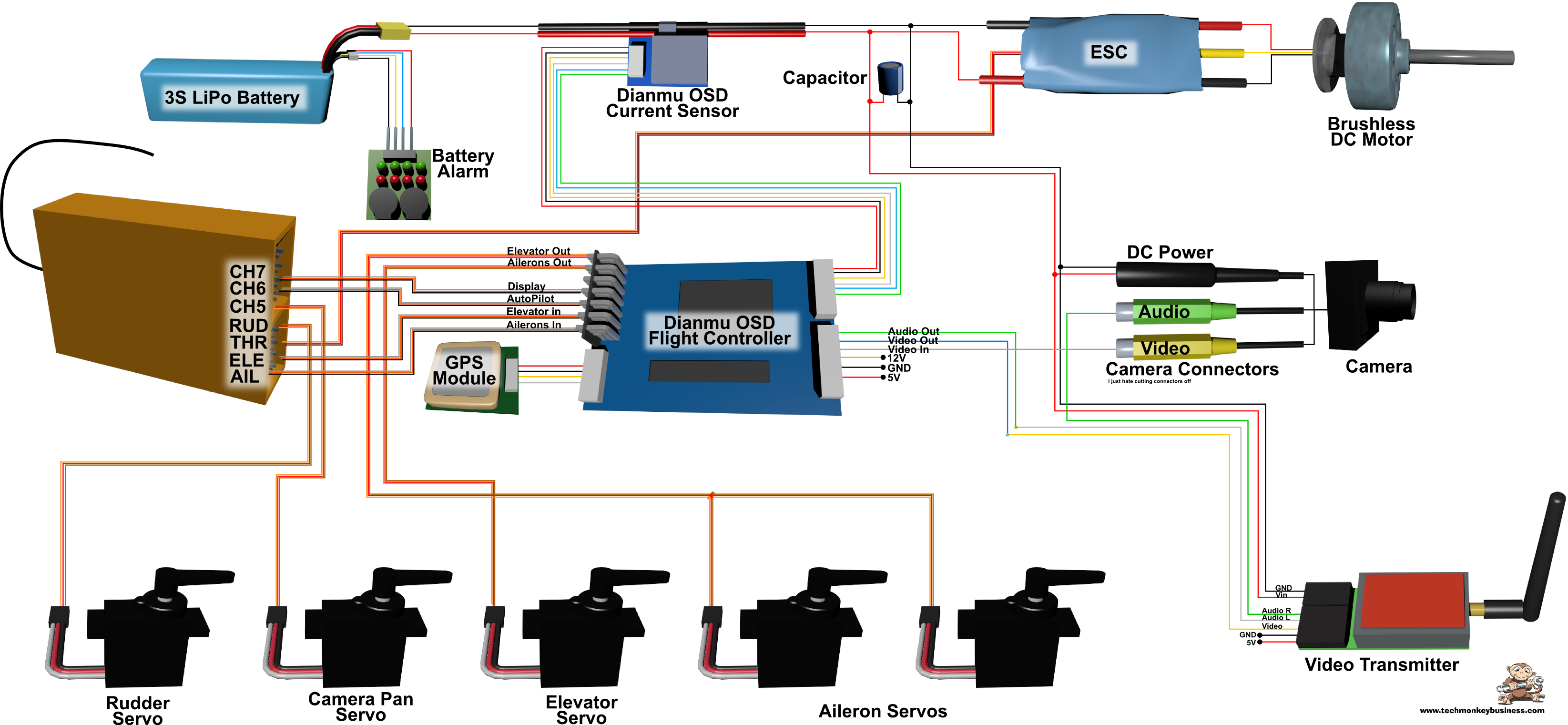
Connections between the Dianmu OSD and other onboard systems.
You will see that the Dianmu OSD flight control system only controls the ailerons and elevator. The pilot still retains the ability to use the rudder and throttle even when the flight controller is flying in return-to-home mode. I have yet to see whether I need to set some sort of failsafe throttle level (say 30%) to help it get home if the plane loses the controller signal.
The Dianmu OSD main board includes a connection for an RSSI (Received Signal Strength Indicator). I don’t have one of these and so that connection is left bare.
The camera includes a regulator in its connectors which allowed me to supply it directly from the main battery. The alternative would be to supply it from either the Dianmu OSD main board using one of the voltage out ports there or from the video transmitter which can supply 5V. My preference is to keep it clean, by supplying it from the main battery, thereby reducing the load on any of the other components that could be used to supply it.
Channels 6 and 7 on the transmitter are used to control the Dianmu OSD’s mode and navigate the menu system at startup. On the Turnigy 9XR transmitter I am using, the Autopilot mode is selected by a three position switch, and the OSD view mode is selected using one of the pots.
The system works. Now I just need a non-windy day to get it into the air and see if I have eliminated the OSD view breakup problem.